

 简体中文
简体中文 English
 日本語
日本語 한국어
한국어 Español
 русский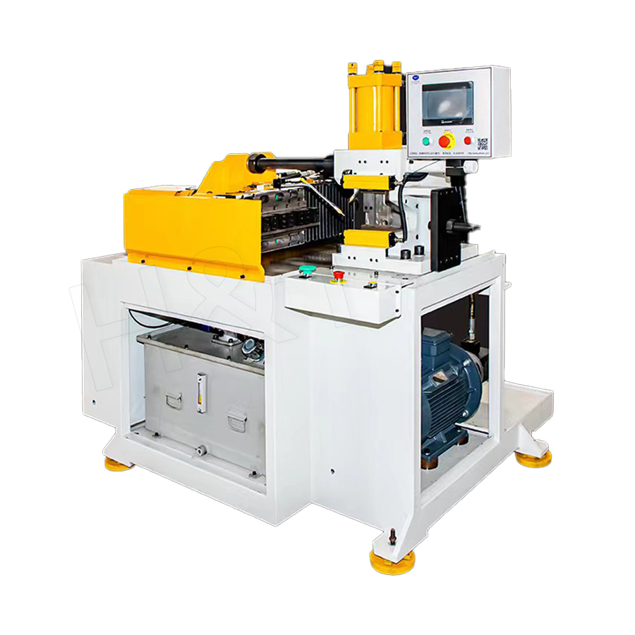
No. 196, Lifa Avenue, Haian City, Nantong, Jiangsu Province, China

News Category
Product Category
Tube End Forming Guide: Process Choices, Tooling Types, and Key Tolerances
A 6 mm bead rolled onto the end of a hydraulic return line can measure perfectly on the bench and still weep fluid at 180 bar. The bead diameter is on print, the surface is clean, and the leak trace still points straight at the joint. In most of these cases the problem is not the operator or the material lot. The bead simply sits 0.3 mm off the tube centerline, and a hose clamp cannot compress evenly around an eccentric ridge.
Tube end forming rewards decisions made before the tool ever touches the tube: which form the joint actually needs, whether that form should be produced by ram forming or segmented tooling, and how repeatable the machine stays across thousands of cycles. Get those three right and most leaks, split flares and rework disappear. Get them wrong and no amount of final inspection will save the batch, because the failure is built into the geometry.
Content
- 1 What Tube End Forming Actually Changes
- 2 Ram Forming Versus Segmented Tooling
- 3 Standard End Forms and the Dimensions That Decide Quality
- 4 Where End Forming Sits in the Production Sequence
- 5 What to Specify When Buying Tube End Forming Equipment
- 6 Defects, Their Usual Cause, and the Fix
- 7 Automation and Inline Integration
What Tube End Forming Actually Changes
Bending moves the centerline of a tube. End forming reshapes the last few millimeters of it. The purpose is always the same: create a sealing surface, a mechanical stop, or a geometry that another component can grip, weld or clamp against. The list of forms is longer than most buyers expect, and each one solves a different joint problem.
| Form | Geometry created | Typical joint use |
|---|---|---|
| Beading | Raised circumferential ridge | Hose retention, clamp stops, leak resistant connections |
| Flaring | Cone, bell or ball shaped seat | Flare fittings, brake and fuel lines, gas connections |
| Reduction | Smaller diameter section at the end | Stepped inserts, telescoping joints, weld sockets |
| Expansion | Larger diameter section at the end | Slip fit joints, sleeve assembly, bearing seats |
| Knurling | Textured band on the outside | Grip surfaces, press fits, adhesive bonding |
| Grooving and rolling | Rolled groove or spun groove | Clamp couplings, quick connect retainers |
| Coping and notching | Contoured end matched to a mating tube | Welded T joints in frames and rails |
Chamfering and deburring usually travel with end forming because they prepare the same real estate. A tube that is cut, chamfered, deburred and then end formed on one line avoids the double handling that drives up cost per part in low volume shops.
Ram Forming Versus Segmented Tooling
Ram forming drives a shaped punch axially into the tube end. The material flows outward or inward against the punch profile. It is fast, the tooling is simple, and cycle times are short. The trade offs are real: the outside of the form tends to thin, concentricity depends heavily on how well the tube is guided, and a single punch produces a single form. Change the bead diameter and you change the punch.
Segmented tooling uses a set of fingers that expand or contract, working either from the inside out or the outside in. Because the segments are controlled individually and can be released from the part before retraction, they handle forms that a solid punch cannot produce, including undercuts, deep grooves, tight radius beads and combinations of two forms in one stroke. Concentricity and cosmetic quality are noticeably better, and the same head can often run several different profiles by changing the program rather than the hardware.
When each method earns its place
- High volume, simple symmetrical expansion or reduction: ram forming is usually the lower cost answer.
- Tight eccentricity limits, cosmetic visible parts, or forms near a bend: segmented tooling pays for itself quickly.
- Thin wall tube with a diameter to wall ratio above roughly 30 to 1: segmented support reduces the risk of wrinkling and collapse.
- Frequent product changeover: numeric controlled segmented heads cut changeover from hours to minutes.
- Hard or work hardened material such as stainless or cold drawn steel: slower forming speeds and better support matter more than raw force.
Standard End Forms and the Dimensions That Decide Quality
Many end forms exist because a fitting standard already defines them. SAE 45 degree flare fittings, 37 degree JIC flares, double flares and ball flares each have a defined seat geometry. Beading families include the common single bead, the SAE bead used on hose nipples, the inverted bead, and Marmon and Norma style ball forms used with specific clamp systems. Getting the seat angle or the bead profile wrong rarely shows up at assembly. It shows up weeks later as a weeping joint.
Practical shop tolerances for tube end forming usually sit in these ranges:
- Bead diameter: within plus or minus 0.1 mm on small diameter tube, wider on large diameter work.
- Flare seat angle: within 1 degree of nominal, with no visible chatter marks on the seat.
- Wall thinning at the formed section: kept under 15 percent of nominal wall.
- Eccentricity between the form and the tube centerline: under 0.25 mm on typical hydraulic and fluid line work.
- Form length: within plus or minus 0.3 mm so that downstream clamps and clips seat correctly.
Where End Forming Sits in the Production Sequence
Sequence errors cause more scrap than tool wear does. The order below is the one that holds up across most tube fabrication work.
- Cut to length with a saw or laser, holding length within plus or minus 0.5 mm so that every forming stroke sees the same amount of material.
- Chamfer and deburr both ends to remove the cut burr that would otherwise be pressed into the formed surface.
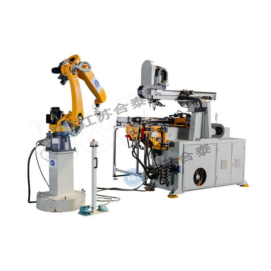
- Bend the tube, using processes such as CNC bending where repeatability matters, and keep the bender clamps away from any finished form.
- End form after bending whenever the form sits close to a bend, because bender clamp jaws can crush a finished bead or distort a flare seat.
- End form before bending only when the bender grips a long straight section far from the formed end, and the form itself is used as a locating feature.
- Clean, dry and inspect the formed end before the part reaches assembly.
What to Specify When Buying Tube End Forming Equipment
Machine selection should follow the part family, not the other way around. A tube end forming machine that covers a 4 mm to 50 mm outside diameter range with a hydraulic ram will handle simple beading and reduction work efficiently. If the part mix includes grooves, undercuts, spinning or flaring in the same cycle, a numerically controlled segmented head is the more honest starting point, and an all in one station that combines stamping, rotary grooving and chamfering removes an entire handling step from the route.
Bring these numbers to any supplier conversation:
- Outside diameter range, wall thickness range, and the material grades you actually run.
- Form types required, with a drawing of each profile and its tolerance band.
- Cycle time target per end, and whether both ends are formed in one pass or two.
- Tooling changeover time and how many profile changes a typical week contains.
- Acceptable eccentricity, surface finish and wall thinning limits.
- Whether the machine must link into an automatic feed, conveyor or robot cell.
 Tube End Forming Machine1. PLC unit control, touch screen, easy to operate, flexible settings, and easy to learn; 2. High-precision linear guide rails ensure smooth propulsion; 3. Can be equi...View Product →
For higher volumes, a continuous die automated tube end former runs the forming sequence inside a progressive die arrangement, which keeps the part located from the first stroke to the last and removes the re-clamping error that shows up on manual stations.
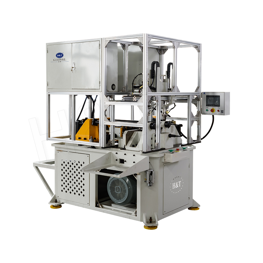
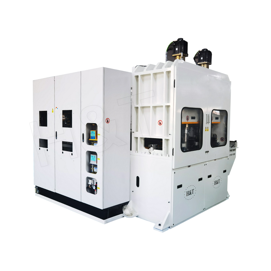
 Continuous Die Automated Tube End FormerThe Continuous Die Automated Tube End Former Machine is a fully automated industrial machine designed specifically for upsetting the ends of tubes. The machine feature...View Product →
Where the requirement is a flared or spun seat rather than a pressed form, a dedicated spinning and flaring machine gives the controlled axial feed and rotational speed needed to keep seat angle and surface finish inside tolerance.
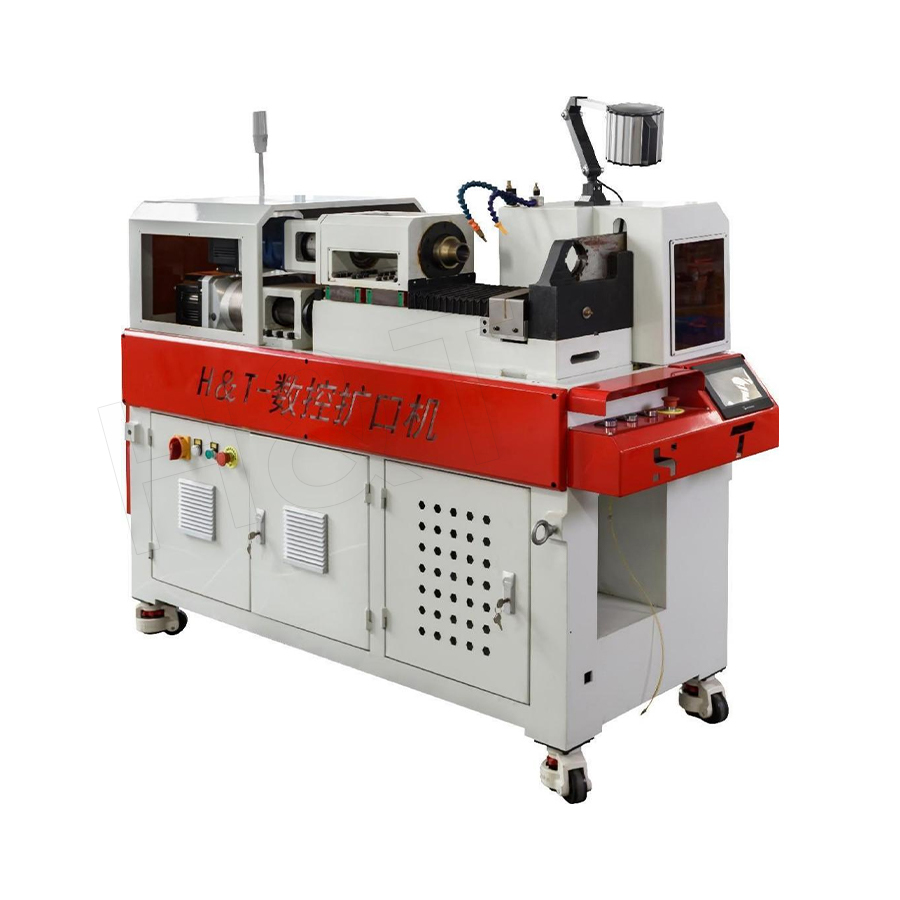 NC Spinning Flaring MachineThe NC Spinning Flaring Machine is a high-efficiency, precise, and intelligent piece of equipment specifically developed for flaring, shrinking, and flanging processes...View Product →
Defects, Their Usual Cause, and the Fix
Most end forming defects repeat in recognizable patterns. Reading them correctly shortens the troubleshooting loop considerably.
| Defect | Likely cause | Correction |
|---|---|---|
| Off center bead | Worn ram guide or die block out of alignment | Check guide bore clearance and recenter the die |
| Cracked or split flare | Ram speed too high, wrong lubricant, work hardened material | Reduce forming speed, verify material temper, change lubricant |
| Wrinkled reduction | Unsupported length too long ahead of the die | Shorten the unsupported span, add segmented support |
| Ovality after expansion | Expansion ratio too aggressive in one pass | Split into two passes or anneal between passes |
| Scoring and galling | Dirty or polished out tooling, dry contact | Polish segments, clean tooling, restore lubrication |
Automation and Inline Integration
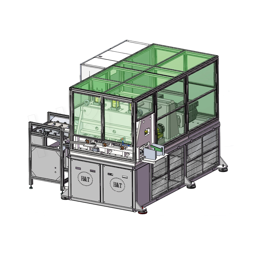
End forming stops being a standalone operation once volumes justify an automated line. Cutting, chamfering, end forming and inspection can be linked with automatic transfer, so parts move without manual re-clamping. The gain is not only labor. It is the elimination of the positional variation that appears every time a finished part is picked up and set down again.
Two practical points apply to any automated arrangement. First, the end forming station must hold its zero across a full shift, because there is no operator watching the first part of every cycle. Second, a reject chute and a simple measurement check should exist inside the line, since defects caught three stations later cost far more to unwind. Teams evaluating this kind of layout often start with a general overview of automation line architecture before specifying individual stations.
Tube end forming is one of the few tube processes where a tenth of a millimeter decides whether a joint seals for a decade or leaks on the first pressure test. The form type follows from the fitting standard, the tooling method follows from the tolerance and the material, and the machine follows from the part family and the volume. Working through those three in order keeps specification conversations short and prevents expensive tooling from being built for a form that a standard fitting already defines.
If a current part is failing at the joint, or a new tube assembly needs a forming process chosen from scratch, it is worth putting the drawing, material and volume target in front of people who build these machines every day. You can talk through a specific forming job with the team and get a tooling and cycle time recommendation based on the actual profile rather than a catalog range.
Featured Products
A Complete Range of Tube Processing Solutions
Precision Tube Bending
 Ready To Customise
Your Bent Tube Products?

Ready To Customise Your Bent Tube Products?
Proprietary software, smart control systems, and 50+ patents ensure more efficient and intelligent production at every step.
Copyright © 2025 by Gipfel Precision Machinery Co.,Ltd All Rights Reserved. Privacy Precision Tube Machinery Manufacturer | Pipe Forming, Cutting, End Forming Solutions
