 English
 日本語
日本語 한국어
한국어 Español
 русский
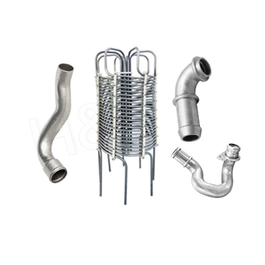
No. 196, Lifa Avenue, Haian City, Nantong, Jiangsu Province, China
News Category
Product Category
What is CNC Bending?
Content
- 1 What Is CNC Bending?
- 2 Advantages of CNC Bending
- 2.1 High Dimensional Accuracy
- 2.2 Superior Repeatability Across Large Runs
- 2.3 Multi-Plane Complex Bending in One Cycle
- 2.4 Rapid Changeover Between Part Programs
- 2.5 Consistent Wall Thickness and Surface Quality
- 2.6 Integration With Automated Production Lines
- 2.7 Reduced Scrap and Lower Total Cost Per Part
- 3 Is CNC Bending Stronger Than Metal Pipe Bending?
- 3.1 What Actually Determines Strength in a Bent Pipe
- 3.2 Wall Thinning: CNC Bending vs. Conventional Bending
- 3.3 Ovality Control
- 3.4 Fatigue Life: The Role of Wrinkle-Free Inner Radius
- 3.5 Is There Any Case Where Conventional Bending Is Stronger?
- 3.6 Practical Conclusion for Engineers and Procurement Teams
- 4 CNC Bending vs. PLC Bending: Which Should You Choose?
- 5 How CNC Bending Machines Work: Principles Explained
What Is CNC Bending?
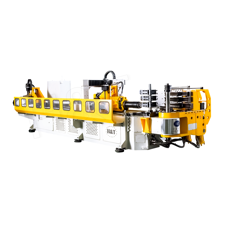
CNC bending is a computer-numerically-controlled process that shapes metal or plastic pipes and profiles into precise, multi-angle forms without manual repositioning. A single-head CNC bending machine uses a full servo drive system and precision mechanical structure to execute complex bending sequences automatically, delivering consistent accuracy across every part.
Unlike manual or hydraulic bending, the machine reads a digital program, moves the pipe to the correct feed length, rotates it to the right plane, and applies the specified bend angle — all in one continuous cycle. This makes CNC bending an indispensable technology in modern automated production lines.
Core Definition and Scope
CNC stands for Computer Numerical Control. In the context of pipe bending, it means the machine's axes — feed length, bend angle, pipe rotation, and clamping pressure — are all governed by a digital controller rather than by hand wheels or mechanical stops.
A typical single-head CNC bending machine operates on at least five synchronized servo axes: bend angle (Y), feed length (Z), pipe rotation (B), clamping (C), and mandrel retraction (W). High-end models add more axes for boosting and pressure-die control.
- Pipe outer diameter range: typically 6 mm – 220 mm, depending on machine class.
- Wall thickness capability: from thin-wall (t/D ≈ 0.02) to heavy-wall structural tube.
- Bend radius: as tight as 1× pipe diameter (1D) with the correct tooling and mandrel.
- Materials processed: carbon steel, stainless steel, aluminum alloy, copper, titanium, and engineering plastics.
How CNC Bending Differs From Conventional Bending
Conventional pipe bending relies on mechanical stops, hand-set angle gauges, and operator skill to position each bend. Every change in angle or plane requires the operator to reset stops and re-clamp the pipe. CNC bending replaces all of that with a stored program.
| Criterion | Conventional Bending | CNC Bending |
|---|---|---|
| Angle accuracy | ±1° – ±2° | ±0.1° |
| Feed-length accuracy | ±1 mm – ±2 mm | ±0.1 mm |
| Multi-plane bends | Manual re-clamping needed | Automatic in one cycle |
| Setup time (new part) | 30 – 120 min | 5 – 15 min |
| Operator skill required | High | Moderate (programming) |
| Repeatability (Cpk) | ≈ 0.8 | ≥ 1.33 |
Key Industries and Typical Applications
CNC bending machines are found wherever a pipe must follow a complex 3-D path and dimensional tolerance cannot be compromised.
- Automotive parts: brake lines, fuel lines, air-conditioning tubing, exhaust manifolds, and roll-cage structures — all produced to tolerances as tight as ±0.5 mm on assembled length.
- Shipbuilding: hydraulic control lines, handrails, deck-fitting pipes, and engine-room piping that must fit confined spaces exactly.
- Energy pipelines: offshore manifold spools, subsea umbilicals, and process-plant instrument tubing where pressure integrity depends on consistent wall thickness.
- Precision instruments: medical device frames, laboratory gas lines, and aerospace hydraulic circuits.
- Furniture and architecture: stainless steel handrails, chair frames, and decorative structural elements.
Key Components of a CNC Bending Machine
Understanding the machine's anatomy helps clarify what "CNC bending" actually involves at the hardware level.
Servo Drive System
Each motion axis is powered by a dedicated AC servo motor with an absolute encoder. The encoder feeds real-time position data back to the CNC controller at update rates of 1 kHz or faster, enabling the closed-loop corrections that give CNC bending its accuracy.
Bending Die Set
The die set consists of a bend die (the radius form), a clamp die (holds the pipe during bending), and a pressure die (supports the trailing straight section). Multi-stack turret heads allow the machine to carry up to six different radius/diameter combinations and switch between them automatically.
Mandrel and Wiper
For thin-wall or tight-radius bends, a mandrel is inserted into the pipe interior to prevent collapse, while a wiper die prevents wrinkle formation on the inner radius. The mandrel retraction axis (W) is servo-controlled to pull back at precisely the right moment in the bend cycle.
CNC Controller and HMI
The industrial CNC controller stores complete bending programs (YBC data sets — angle, feed, rotation — for every bend in a part). The touchscreen HMI lets operators input part data, simulate the bending sequence in 3-D, and monitor axis status in real time.
Summary
CNC bending is the standard for any application that demands consistent, complex, multi-plane pipe geometry at production speed. Its combination of servo precision, programmable control, and automated tool-switching makes it far more capable and repeatable than any manual or semi-automatic alternative — which is why it has become a cornerstone of modern automated manufacturing.
Advantages of CNC Bending
The primary advantages of CNC bending are high precision (±0.1° angle, ±0.1 mm feed length), excellent repeatability, fast changeover, and the ability to complete complex multi-plane bends in a single automatic cycle. Together, these qualities reduce scrap, cut labor costs, and shorten delivery times in a way that no manual or conventional bending method can match.
The following sections break down each advantage with concrete figures and real-world context drawn from automotive, energy, and precision-instrument manufacturing.
High Dimensional Accuracy
A full servo drive system with absolute encoders gives a CNC bending machine closed-loop control over every motion axis. The result is angle accuracy of ±0.1° and feed-length accuracy of ±0.1 mm — roughly 10–20× better than mechanical-stop or hydraulic machines.
In automotive brake-line production, for example, a 3-D tube with seven bends must assemble onto a chassis clip pattern whose total positional tolerance is only ±0.5 mm. CNC bending routinely meets this requirement on every part; conventional bending requires 100% inspection and frequent re-work.
Superior Repeatability Across Large Runs
Repeatability is the ability to produce identical parts in piece 5,000 that match piece 1. Because CNC bending reads the same digital program every cycle and closed-loop servo feedback corrects for any drift, process capability indices (Cpk) of ≥ 1.33 are standard — a threshold that qualifies for automotive Tier-1 supply.
Manual bending, by contrast, is subject to operator fatigue, tool wear, and inconsistent clamping pressure, typically yielding Cpk ≈ 0.8, which means a statistically significant fraction of parts fall outside tolerance.
Multi-Plane Complex Bending in One Cycle
A CNC bending machine can execute a complete 3-D part — feed, rotate, bend, feed again — without the operator touching the pipe between bends. The pipe rotation axis (B) repositions the tube to the correct plane automatically between each bend.
A typical automotive exhaust manifold with five bends in three planes takes approximately 45 seconds per piece on a CNC machine. The same part on a manual bender requires 4–6 minutes and multiple repositioning steps that each introduce error.
Rapid Changeover Between Part Programs
Switching from one part to another on a CNC bending machine means recalling a stored program and, if necessary, swapping a die set. On machines with a multi-radius turret head, no physical die change is needed at all when the new part uses a radius already mounted.
- Program recall: under 60 seconds
- Single-radius die swap: 10 – 15 minutes
- Conventional bender re-setup: 30 – 120 minutes
This speed makes CNC bending cost-effective even for small batches of 20–50 pieces, whereas manual bending's long setup time pushes the economic break-even point much higher.
Consistent Wall Thickness and Surface Quality
Servo-controlled bending speed, pressure-die force, and mandrel retraction timing work together to minimize wall thinning on the outer radius and wrinkling on the inner radius. A well-set CNC machine keeps outer-radius wall thinning below 15% even on 1.5D bends — the threshold required by most pressure-system standards.
Consistent bending speed also reduces surface scratching, which matters in stainless-steel handrail and architectural tube production where aesthetics are as important as geometry.
Integration With Automated Production Lines
CNC bending machines communicate via standard industrial protocols (EtherCAT, PROFIBUS, or Ethernet/IP), enabling them to receive part programs directly from MES/ERP systems and to pass quality data upstream to SPC software. This connectivity supports:
- Automatic program download from a central server when a barcode or RFID tag is scanned.
- Robot-loaded and -unloaded cells running lights-out for extended periods.
- Real-time springback compensation using laser measurement feedback on the finished bend.
These capabilities are simply not available on conventional benders and represent one of the most significant competitive advantages of CNC bending in high-volume manufacturing.
Reduced Scrap and Lower Total Cost Per Part
When accuracy and repeatability are high, fewer parts fail inspection. In a typical production environment, switching from manual to CNC bending reduces scrap rates from 3–8% to under 0.5%. On high-value materials like titanium or stainless alloy, that scrap reduction alone can pay back the machine investment in 12–18 months.
Add in labor savings from reduced inspection time and rework, and the total cost per bent tube on a CNC machine is typically 30–50% lower than on a manual bender at volumes above roughly 200 parts per shift.
Is CNC Bending Stronger Than Metal Pipe Bending?
CNC bending does not weaken a metal pipe more than conventional bending — in fact, its precise control over bending speed, pressure-die force, and mandrel position typically produces a stronger, more consistent bend with less wall thinning and fewer defects. Strength in a bent pipe is determined by material properties, bend geometry, and process control — and CNC bending excels at all three process variables.
What Actually Determines Strength in a Bent Pipe
The structural strength of a bent pipe section is governed by three main factors:
- Wall thinning on the outer radius — bending stretches the outer wall; if it thins too much, burst pressure drops.
- Ovality of the cross-section — a flattened cross-section reduces flow area and collapse resistance.
- Wrinkling or creasing on the inner radius — wrinkles are stress concentrators and fatigue initiation sites.
CNC bending addresses all three more effectively than manual methods because every parameter that influences them — bend speed, pressure-die load, mandrel position, and springback over-bend — is servo-controlled and reproducible.
Wall Thinning: CNC Bending vs. Conventional Bending
Wall thinning is unavoidable in any rotary-draw bending process. The question is how much and how consistent it is. Industry pressure codes (ASME B31.3, EN 13480) specify maximum allowable thinning — typically 12.5% for process piping.
| Process | Average Thinning | Worst-Case Thinning | Part-to-Part Variation |
|---|---|---|---|
| Conventional hydraulic bending | 13 – 18% | up to 22% | ±4 – ±6% |
| CNC servo bending | 9 – 13% | under 15% | ±1 – ±2% |
Lower average thinning means higher retained burst pressure. The smaller part-to-part variation means that every single pipe stays within the code allowance, not just the average.
Ovality Control
Ovality (cross-sectional distortion) is expressed as a percentage: (D_max – D_min) / D_nominal × 100. Standards like ISO 15590-1 for oil-and-gas induction bends limit ovality to 3% or less.
CNC bending with a correctly sized mandrel and wiper die consistently achieves ovality under 2%, even at 1.5D bend radius. Conventional bending without a mandrel often exceeds 5% at the same radius — a level that fails most structural and pressure standards.
Fatigue Life: The Role of Wrinkle-Free Inner Radius
In applications subject to cyclic loading — vehicle exhaust, hydraulic lines, subsea risers — fatigue life is the critical strength metric. Wrinkles on the inner radius act as stress concentrators and are the dominant fatigue initiation site in poorly made bends.
CNC servo control of the wiper die load and bend speed eliminates the stick-slip motion that causes wrinkles in hydraulic benders. In comparative fatigue tests of stainless-steel hydraulic tubing (OD 25 mm, WT 1.5 mm, 1.5D bend), CNC-bent specimens showed 40–60% longer fatigue life than hydraulically bent specimens at the same stress amplitude, due solely to the absence of inner-radius wrinkling.
Is There Any Case Where Conventional Bending Is Stronger?
For very large-diameter, thick-wall pipe (e.g., OD > 300 mm, WT > 20 mm), induction bending or hot-push bending is preferred because the forces involved exceed what rotary-draw CNC machines are designed for. These processes can produce high-integrity bends in line pipe and structural sections.
However, within the operating range of CNC bending machines (typically up to OD 220 mm), CNC bending consistently produces bends with equal or greater structural integrity compared to manual or hydraulic methods, primarily because of its superior control over thinning, ovality, and surface quality.
Practical Conclusion for Engineers and Procurement Teams
When specifying pipe bends for structural, pressure, or fatigue-critical applications:
- Specify maximum allowable wall thinning (e.g., ≤ 12.5%) and ovality (e.g., ≤ 3%) — both are more reliably achieved by CNC bending.
- For dynamic/fatigue applications, require a wrinkle-free inner radius — only CNC servo control provides this consistently.
- For pipe OD > 220 mm or WT > 20 mm, evaluate induction bending rather than rotary-draw CNC bending.
In summary, CNC bending is not just as strong as conventional metal pipe bending — it is typically stronger because it delivers tighter control over the physical defects that reduce structural capacity.
CNC Bending vs. PLC Bending: Which Should You Choose?
CNC bending is better for complex multi-bend parts, tight tolerances, and frequent changeovers; PLC-controlled bending is better for simple, high-volume, single-radius production where lowest machine cost matters most. The choice depends on part complexity, batch size, tolerance requirements, and total cost of ownership — not on which technology is inherently superior.
Understanding the Difference in Control Architecture
A PLC (Programmable Logic Controller) bending machine uses a ladder-logic or function-block program to sequence machine actions: clamp → bend to limit switch → retract → unclamp. The position feedback is typically from simple proximity sensors or basic encoders. PLC benders are very reliable for fixed, repetitive sequences but are not designed for multi-axis interpolation or on-the-fly parameter adjustment.
A CNC bending machine uses a dedicated motion controller that interpolates multiple servo axes simultaneously. It stores complete part programs (Y bend angle, Z feed length, B rotation for every bend in the part) and can execute them in any order, with springback compensation applied automatically on each axis.
Head-to-Head Comparison
| Feature | PLC Bending | CNC Bending |
|---|---|---|
| Angle accuracy | ±0.5° – ±1° | ±0.1° |
| Multi-plane bends | Requires manual rotation | Fully automatic |
| Part program storage | Limited (10 – 50 recipes) | Thousands of programs |
| Springback compensation | Manual adjustment | Automatic per axis |
| Changeover time | 20 – 60 min (reset stops) | < 5 min (program recall) |
| Robot / MES integration | Limited or custom | Standard protocols |
| Machine purchase cost | Lower (20 – 50% less) | Higher |
| Best application fit | Simple, high-volume, 1-radius | Complex, multi-radius, mixed |
When PLC Bending Is the Right Choice
PLC bending machines make economic sense in specific scenarios:
- Single-radius, single-plane production with very high volume and no product variety — for example, bending thousands of identical U-bolts per shift.
- Low-tolerance applications where ±1° is acceptable — structural conduit bending for building services, for instance.
- Budget-constrained workshops that produce simple parts and cannot justify the capital cost of a full CNC system.
- Backup or pre-forming stations in a cell where a CNC machine handles finishing.
When CNC Bending Is the Right Choice
CNC bending is clearly superior in these situations:
- Multi-bend, multi-plane parts — any automotive tube with more than two bends in different planes demands CNC for efficient production.
- Tight-tolerance applications — instrument tubing, hydraulic lines, and medical device components that require ±0.1° and ±0.5 mm positional accuracy.
- Frequent changeovers — mixed production of 20 – 50 different part numbers per day, where PLC setup time would consume most of the shift.
- Automated cell integration — lines using robots, vision systems, and MES connectivity require CNC's standard communication interfaces.
- Springback-sensitive materials — high-strength steel (≥ 550 MPa), titanium, and precipitation-hardened alloys, where springback varies with batch and cannot be corrected manually in real time.
Total Cost of Ownership: The Real Financial Comparison
A PLC bending machine may cost 30–50% less to purchase than an equivalent CNC machine. However, total cost of ownership over a 10-year period often favors CNC when part complexity and variety are considered:
- Scrap cost: PLC bending generates 3–8% scrap vs. under 0.5% for CNC.
- Labor: CNC machines can run semi-autonomously; PLC benders typically require one operator per machine at all times.
- Rework and inspection: CNC's higher first-pass yield reduces downstream QC costs significantly.
For shops running more than 10 different part numbers per week on medium-complexity parts, CNC bending typically achieves payback within 2–3 years versus the lower-cost PLC alternative.
Verdict
There is no universally "better" technology. Choose PLC bending for simple, high-volume, price-sensitive production. Choose CNC bending for complex geometry, precision tolerances, frequent changeovers, and automated line integration. If your parts have more than two bends, or if you change parts more than five times per shift, CNC bending will almost certainly deliver better economics over any multi-year horizon.
How CNC Bending Machines Work: Principles Explained
A CNC bending machine works by reading a stored part program that specifies the bend angle (Y), pipe feed length (Z), and pipe rotation (B) for each individual bend, then driving dedicated servo axes to execute every movement in precise sequence — all without operator intervention between bends. The result is a complete 3-D bent component produced to tight tolerances in a single automatic cycle.
The YBC Coordinate System: How the Machine Thinks About a Bend
Every bend in a CNC bending program is defined by three parameters, collectively called the YBC data set:
- Y – Bend angle: the angle to which the pipe is bent at this station (e.g., 90.00°, resolved to ±0.1°).
- B – Pipe rotation: how much the pipe is rotated around its own axis before the next bend (0–360°, resolved to ±0.1°).
- C – Feed length (sometimes labeled Z): how far the pipe is advanced from the previous bend to the start of the next bend (resolved to ±0.1 mm).
A part with seven bends has seven YBC rows in its program. The controller processes them sequentially, moving each axis to its target value before initiating the bend cycle.
Step-by-Step Working Sequence
Step 1 — Program Loading and Simulation
The operator selects or downloads the part program on the touchscreen HMI. Most modern CNC bending machines offer 3-D graphical simulation: the controller renders the complete tube path before any metal moves, allowing the programmer to check for collisions between the pipe, tooling, and machine frame.
Step 2 — Pipe Loading and Clamping
The raw pipe is placed in the chuck or collet at the rear of the machine. The chuck grips the pipe with a servo-controlled clamping force calibrated to prevent slipping without denting soft materials. For automated lines, a robotic loader performs this step.
Step 3 — Feed (Z/C Axis Movement)
The carriage servo drives the pipe forward by the C value from the program — for example, 245.0 mm — positioning the correct pipe length in front of the bend die. Absolute encoder feedback ensures the position error is under ±0.1 mm at the end of the move.
Step 4 — Pipe Rotation (B Axis)
The chuck rotates the pipe to the B angle specified for this bend — for example, 127.5° from the previous bend plane. This positions the pipe so the bend will occur in the correct spatial plane. Rotation accuracy of ±0.1° is critical: a 0.5° rotation error on a tight-radius bend translates to a positional error of several millimeters at the pipe end.
Step 5 — Die Clamping and Mandrel Advance
The clamp die closes onto the pipe against the bend die with a programmed force. If a mandrel is used, it is advanced by the W axis to the correct position inside the pipe — typically with the leading ball at or slightly past the tangent point of the bend. The wiper die is also positioned against the pipe's inner radius.
Step 6 — Bending (Y Axis with Springback Compensation)
The bend arm rotates to Y + springback_compensation degrees. Springback — the elastic recovery of the pipe after the forming force is removed — must be over-bent to achieve the target angle. For example, if the target is 90° and the material springback for this alloy and wall thickness is 3.5°, the machine bends to 93.5°. The controller stores springback compensation values per material grade, diameter, and radius, and applies them automatically.
Bending speed is also servo-controlled — typically 3 – 20°/second, selected based on material and radius. Faster bending risks wrinkling; slower bending wastes cycle time.
Step 7 — Mandrel Retraction and Die Opening
At a programmed point in the bend stroke (typically 75–85% of the target angle), the mandrel is retracted by the W axis to prevent it from being locked in the finished bend. The clamp die then opens, and the bend arm returns to its home position.
Step 8 — Repeat for All Remaining Bends
Steps 3 through 7 repeat for each subsequent bend in the program. For a seven-bend automotive tube, the complete cycle from first feed to last bend open takes 60 – 90 seconds on a modern CNC bending machine.
Closed-Loop Servo Control: The Engine of Precision
The accuracy of the entire process rests on the closed-loop servo system. Each axis consists of:
- AC servo motor with torque output matched to the axis load.
- Absolute multi-turn encoder (typically 17–23 bit resolution), which retains position even after power-off.
- Servo drive that compares encoder feedback to the CNC controller's command at update rates of 1 kHz or higher, applying corrective current in real time.
- CNC motion controller that plans velocity profiles (trapezoidal or S-curve) to minimize mechanical shock while maintaining accuracy.
This architecture means the machine self-corrects for thermal expansion of ballscrews, gear backlash, and load variation — sources of error that accumulate to several millimeters on machines without closed-loop feedback.
Springback Compensation in Detail
Springback is one of the most significant variables in pipe bending. It depends on:
- Material yield strength — higher-strength steels spring back more.
- Bend radius — tighter radii spring back less because more of the wall cross-section yields plastically.
- Wall thickness — thicker walls have a higher proportion of elastic core material and spring back more.
- Heat lot variation — yield strength can vary ±10% within a material specification.
Advanced CNC bending systems incorporate adaptive springback learning: the machine bends the first piece, measures the resulting angle (via an angle sensor or laser), compares it to the target, updates the compensation value automatically, and applies it to all subsequent pieces without operator input.
Part Programming: From CAD to Machine
Modern CNC bending machines accept programs in multiple formats:
- Direct YBC entry — the operator types in the Y, B, C values for each bend, derived from the part drawing.
- 3-D CAD import — the machine's software reads a STEP or IGES file of the finished tube, automatically extracts the YBC data, and generates the complete program. This eliminates manual measurement errors.
- Tube inspection reverse calculation — a coordinate measuring arm digitizes a master tube, and the software back-calculates the YBC program. Useful when a drawing does not exist or is in 2-D only.
Once stored, programs are recalled in seconds and can be version-controlled in a central database — allowing the same part to be reproduced years later with identical parameters.
Quality Monitoring During the Bending Process
High-specification CNC bending machines incorporate in-process monitoring:
- Torque monitoring: the bend arm servo torque is logged throughout the bend stroke. A sudden torque spike indicates pipe wall cracking or tool seizure, and the machine stops automatically.
- Angle sensor feedback: an encoder or laser angle sensor measures the actual achieved bend angle after springback and compares it to the program value.
- Data logging: all axis positions, torques, and cycle times are logged per part, providing a traceable production record for industries with strict quality audit requirements (automotive IATF 16949, aerospace AS9100).
This combination of precise motion control, automatic springback compensation, and in-process monitoring is what distinguishes a full servo CNC bending machine from any simpler alternative — and why it is the technology of choice wherever dimensional consistency and structural reliability are non-negotiable.
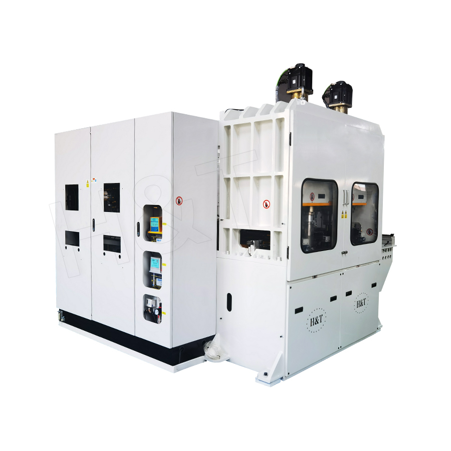
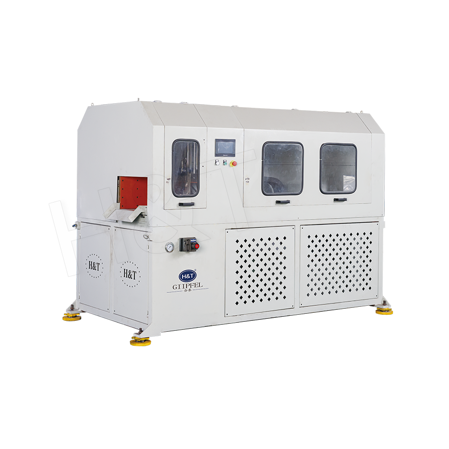
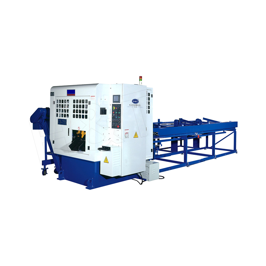
Featured Products
A Complete Range of Tube Processing Solutions
Precision Tube Bending
 Ready To Customise
Your Bent Tube Products?

Your Bent Tube Products?
Proprietary software, smart control systems, and 50+ patents ensure more efficient and intelligent production at every step.
Copyright © 2025 by Gipfel Precision Machinery Co.,Ltd All Rights Reserved. Precision Tube Machinery Manufacturer | Pipe Forming, Cutting, End Forming Solutions
