

 简体中文
简体中文 English
 日本語
日本語 한국어
한국어 Español
 русский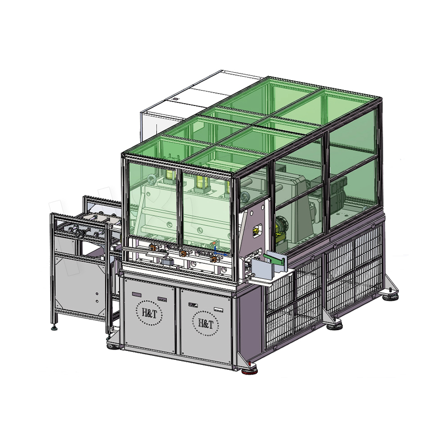
No. 196, Lifa Avenue, Haian City, Nantong, Jiangsu Province, China

News Category
Product Category
How to Make Technical Drawings of CNC Wire Bend Parts That Shops Can Build
Three weeks after a wire form was quoted, the shop still had not cut metal. The RFQ package held a shaded 3D model, a single isometric view, and a note that said bend as required. No one could confirm which way bend four rotated, so the estimator either padded the price or sent the job back. The fix is not a prettier picture. A CNC wire bending drawing is a data package: a bend table with feed, rotation and angle values, a wire specification with tolerance, a bend radius the material can actually take, and a datum an inspector can measure from. Get those four items onto one sheet and the part moves from question mark to purchase order.
Content
- 1 The Minimum Data Set a CNC Wire Bending Drawing Must Carry
- 2 Choosing Views: 2D Flat Layout or 3D Coordinates
- 3 Bend Radius, Material and the Tooling Limit
- 4 Springback: The Number Most Drawings Leave Out
- 5 Where Wire Drawings Fail: Defect Frequency in Real RFQs
- 6 Comparing Drawing Packages Before Release
The Minimum Data Set a CNC Wire Bending Drawing Must Carry
A wire bender makes three motions per bend. It feeds wire to a set length, rotates the wire inside the collet, then advances a forming tool to bend. Every dimension on the sheet should map to feed, rotation, bend or tooling. Anything that cannot be translated into one of those four belongs in a separate document, not in a note balloon. If you want the short version of how the axes and controllers work, our overview of what is CNC bending covers it.
The table below is the data set that keeps a wire form quote clean. The example values suit a 4 mm low carbon or stainless wire formed on a servo bender. Adjust the numbers for your own process, but do not delete the rows.
| Data element | Typical value or example | Why the bender needs it |
|---|---|---|
| Wire diameter and tolerance | 4.00 mm plus or minus 0.05 mm | Sets the tooling groove, feed grip and cut length |
| Material and temper | AISI 304, half hard | Drives minimum radius and springback allowance |
| Cut length | 1240 mm, plus 5 minus 0 | Defines the feed stop and scrap allowance |
| Bend table (feed, rotation, angle) | 250 mm feed, 90 deg rotation, 45 deg bend | Runs the servo sequence bend by bend |
| Inside bend radius | R4.0, one times wire diameter | Selects the forming nose and tool clearance |
| Rotation direction and plane | Clockwise seen from feed end, planes 1 to 4 | Prevents mirrored or reversed parts |
| Datum and measurement origin | End A, bend 1 at 0 deg | Gives inspection a fixed starting point |
| Angle and leg tolerances | Angle plus or minus 0.5 deg, leg plus or minus 0.3 mm | Sets the inspection plan and the accept or reject line |
One element is easy to forget: an A end and B end label. When a part is asymmetric, the difference between end A and end B is the difference between a fit and a scrap bin.
Choosing Views: 2D Flat Layout or 3D Coordinates
If every bend sits in one plane, a 1:1 flat layout plus a linear bend table is enough. Dimension along the centerline, put angles in degrees, show radii to the inside of the bend, and state the cut length once at the bottom of the sheet. Centerline dimensioning ends the argument about whether a number refers to the inside or the outside of the wire.
For multi-plane parts, the isometric view is a communication aid, not a manufacturing instruction. The controlling document becomes a coordinate table listing the XYZ position of each bend point together with a rotation value and a plane reference. Replace left and right with clockwise or counter-clockwise as seen from the feed end, because left depends on which way a person happens to be looking.
Also mark the feed end, the finished end, and the position of any flat, thread or hook feature relative to bend one. A single orientation anchor at the start of the wire removes most mirrored-part errors, and it lets the programmer verify the part before a single meter of wire is consumed.
Bend Radius, Material and the Tooling Limit
The forming nose on the machine becomes the inside radius of the wire, so the tightest radius you can draw is the tightest tool you own. That limit is usually expressed as a multiple of wire diameter, and it changes with tensile strength and temper. Calling R2 on a 6 mm spring steel wire is not ambitious, it is unbuildable without cracking or an extra stress relief step.
Minimum inside bend radius as a multiple of wire diameter
The bars show the minimum inside bend radius as a multiple of wire diameter for five common wire types. Aluminum 5052 in H32 temper tolerates roughly 0.8 times the wire diameter, while a 5 mm low carbon wire needs about R5 and a half-hard 304 stainless wire of the same size needs about R10. The practical consequence is that radius callouts and material callouts have to be checked together rather than one at a time. If a design demands a tighter radius than the bars allow, the realistic options are a softer temper, a smaller wire, or a two-stage form with an intermediate stress relief. The multipliers assume clean, lubricated wire, room temperature forming and a smooth forming nose. Cold drawn wire with surface seams will crack earlier, so add margin when the incoming stock is not fully characterized.
State the radius as an inside radius and place the wire diameter and temper on the same line. Three numbers in one line prevent most of the back and forth that radius callouts generate.
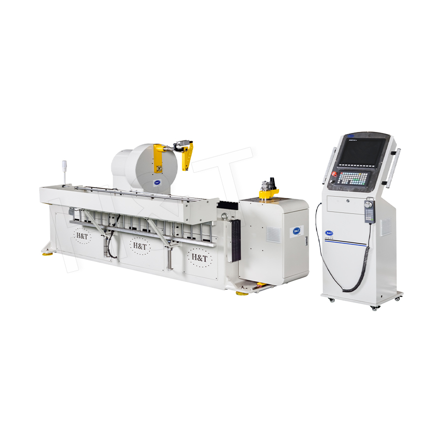
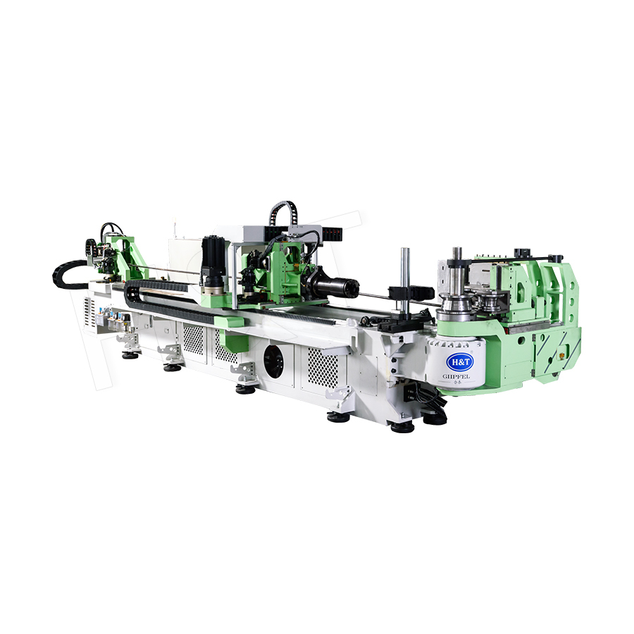 Single Direction Full-servoThe unidirectional all-electric pipe bending machine is the core product of H T's E-series. Utilizing all-electric drive technology, it achieves high-precision unidire...View Product →
Tooling also decides whether the part is even reachable. A bend close to a previously formed leg can collide with the forming arm, so the drawing should show the distance from each bend to the nearest obstruction on both legs.
Springback: The Number Most Drawings Leave Out
Wire springs back when the forming tool retracts. Command a 90 degree bend and a half-hard stainless wire may settle at 87.5 degrees. That is not a machine fault, it is a predictable property of the material driven by yield strength and the ratio of bend radius to wire diameter. Servo benders compensate by overbending, and the drawing should say what the target is so first article is not guesswork.
Overbend allowance for a 90 deg bend, radius equal to twice the wire diameter
The curve plots the overbend allowance needed for a 90 degree bend on a wire with an inside radius equal to twice the wire diameter. At 400 MPa tensile the material is forgiving and about 1 degree of overbend is enough. Past 800 MPa the allowance climbs quickly, reaching roughly 5.5 degrees at 1200 MPa, which is where spring steel and cold worked stainless live. Two consequences follow for the drawing. First, the overbend note should scale with the material rather than being copied from an old sheet. Second, a tolerance of plus or minus 0.5 deg on the finished angle is realistic on a servo bender, but only after the allowance has been dialed in on the first article. Where the curve is steep, the same angle tolerance demands a tighter material specification, because a 100 MPa swing in yield strength moves the finished angle noticeably.
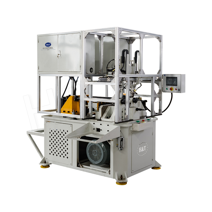
 Pipe/wire Dual-purpose BendingThe Pipe/Wire Dual-purpose Bending Machine, part of the H T series CNC bending equipment, is designed for high-precision bending of aluminum pipes, iron pipes, and var...View Product →
A practical note for the sheet: give the overbend as an allowance, not a hard dimension. Mark it as adjustable on first article, then freeze the corrected value once the inspection report confirms it.
Where Wire Drawings Fail: Defect Frequency in Real RFQs
Reviewing incoming quote packages makes the pattern obvious. The same five omissions appear again and again, and each one adds a clarification round before the estimate can be finished.
Share of wire form RFQs missing each data element
The bars summarize the five omissions that appear most often in incoming wire form RFQs. Missing rotation or bend plane data accounts for 32 percent of clarification rounds, and it is also the most expensive to resolve, because the estimator has to guess at a part that may need a completely different setup. Material temper callouts are absent in roughly a quarter of packages, even though temper changes both the minimum radius and the springback allowance. Radii below the formable minimum show up in 18 percent of drawings, usually because the designer worked from a 3D model without checking wire tooling. Cut length tolerance and datum errors are less frequent, but they surface late, often at first article inspection when the wire is already cut. Fixing the top two categories alone would remove more than half of the back and forth.
Five steps keep a wire drawing out of those categories:
- Draw the centerline first, then dimension legs along it so inside and outside dimensions never mix.
- Fill the bend table completely, one row per bend, with feed, rotation and angle in machine order.
- Check the inside radius against the material multiplier before the drawing leaves the design office.
- Add an overbend allowance note tied to the material, and mark it adjustable on first article.
- Release a centerline DXF alongside the PDF so the programmer can verify leg lengths without re-drawing.
Comparing Drawing Packages Before Release
Three levels of documentation reach most bending shops: a 2D PDF with no bend table, a 2D drawing with a full feed, rotation and angle table, and a 3D STEP model combined with that same table. The radar below scores each package on five criteria that a manufacturing engineer cares about.
Documentation package score, 0 to 100
3D STEP plus bend table 2D drawing plus bend table 2D drawing only
The radar compares three documentation packages against five criteria, scored from 0 to 100. A plain 2D PDF scores poorly on dimensional certainty and first-article accuracy because the bend sequence has to be reconstructed by the programmer. Adding a complete feed, rotation and angle table lifts setup speed and certainty into the 75 to 80 range without changing the model at all. The strongest package, a 3D STEP file paired with the same table, scores above 90 on certainty and first-article accuracy while holding revision effort low. Revision effort rises for the weaker packages because every geometry change restarts the interpretation process and can reset the bend sequence. The pattern is worth remembering: the table does most of the work, and the 3D model confirms it rather than replacing it.
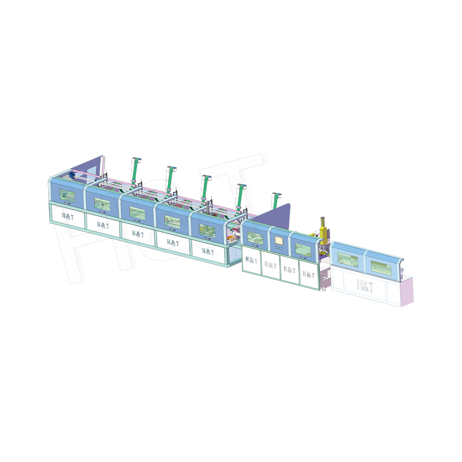
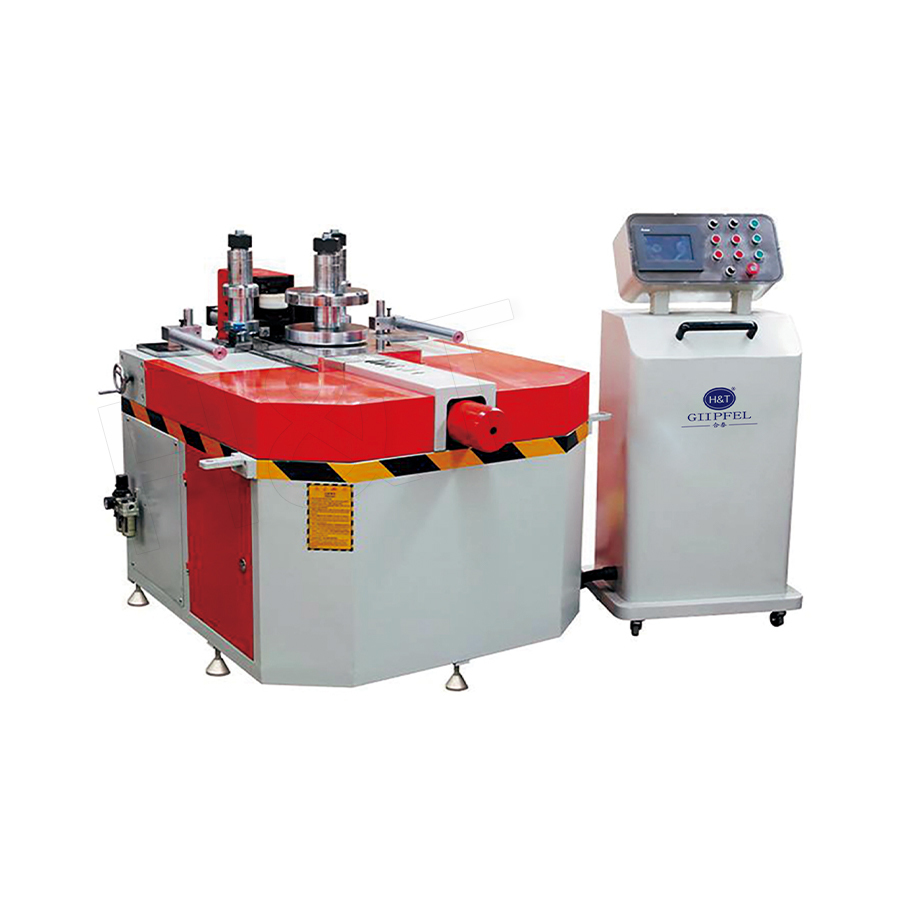 3D Rolling BendingThe 3D Rolling Bending Machine is a high-precision CNC pipe bending and coiling equipment launched by H T, specifically designed for the automated processing of small-...View Product →
Set a boundary the shop can trust: the bend table controls geometry, so the 3D model must stay consistent with it. When the two disagree, the shop will distrust both and the drawing loses its authority.
Technical drawings for CNC wire bending are judged by how little the shop has to ask. Put feed, rotation and bend data in a table, pair it with a wire specification, a formable radius and clear tolerances, then add the overbend allowance as a first-article note. That package turns a quote into a schedule and a prototype into a repeatable part. If you would like a second pair of eyes on the bend table before release, send the drawing to our engineering team and we will mark it up against the tooling that will actually run it.
Featured Products
A Complete Range of Tube Processing Solutions
Precision Tube Bending
 Ready To Customise
Your Bent Tube Products?

Ready To Customise Your Bent Tube Products?
Proprietary software, smart control systems, and 50+ patents ensure more efficient and intelligent production at every step.
Copyright © 2025 by Gipfel Precision Machinery Co.,Ltd All Rights Reserved. Privacy Precision Tube Machinery Manufacturer | Pipe Forming, Cutting, End Forming Solutions
