

 简体中文
简体中文 English
 日本語
日本語 한국어
한국어 Español
 русский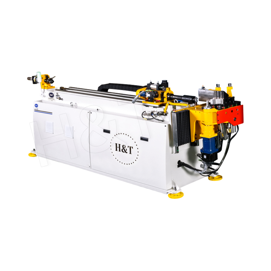
No. 196, Lifa Avenue, Haian City, Nantong, Jiangsu Province, China

News Category
Product Category
How does CNC bending differ from other bending methods?
CNC Bending differs from other bending methods primarily in its use of computer numerical control to automate and precisely govern every parameter of the bending process — including bend angle, rotation, feed length, clamp pressure, and springback compensation — eliminating the operator skill dependency and dimensional variability that characterize manual, hydraulic press, and rotary draw bending performed without CNC control. Where a skilled manual bender might achieve angular repeatability of plus or minus 2 to 3 degrees across a production run, a CNC bending machine consistently holds tolerances of plus or minus 0.1 degrees or better on bend angle and plus or minus 0.5 mm on linear dimensions, producing identical parts from the first piece to the ten-thousandth with no degradation in accuracy. The sections below compare CNC bending against each major alternative method in practical engineering and production terms.
Content
- 1 What CNC Bending Actually Controls That Other Methods Do Not
- 2 CNC Bending vs. Manual Hand Bending
- 3 CNC Bending vs. Hydraulic Press Bending
- 4 CNC Bending vs. Roll Bending
- 5 CNC Bending vs. Induction Bending
- 6 CNC Bending vs. Conventional Rotary Draw Bending Without CNC
- 7 Springback: The Central Challenge That CNC Bending Solves Better Than Any Alternative
- 8 Multi-Stack Tooling and Right-Left Bending: Capabilities Unique to Advanced CNC Machines
- 9 Industry Applications Where CNC Bending Is the Only Viable Method
- 10 Choosing Between CNC Bending and Alternative Methods: A Decision Framework
What CNC Bending Actually Controls That Other Methods Do Not
To understand how CNC bending differs, it helps to identify precisely which variables are computer-controlled in a CNC system and which are left to operator judgment or mechanical setup in alternative methods. The difference is not simply that CNC machines are "automated" — it is that they control specific physical parameters to a precision that human operators and fixed mechanical setups cannot reliably match.
Closed-Loop Angular Control
In a CNC tube or pipe bender, the bend angle is monitored in real time by a rotary encoder on the bend die shaft. As the material wraps around the bend die, the controller continuously reads the actual angle achieved and compares it against the programmed target. If the material's springback characteristics cause the measured angle to diverge from the expected value — which occurs whenever material batch properties vary — the controller adjusts the overbend amount automatically within the same cycle. This closed-loop correction is the single most important distinguishing capability of CNC bending: it produces the correct final angle after springback, not merely the correct tooling position during bending.
Manual and hydraulic bending without CNC control sets the tooling to a fixed position based on an estimated overbend angle calculated from material properties. When the actual material's yield strength differs from the estimate — as it always does to some degree between material batches — the final bent angle differs from the target. The operator must measure the part, adjust the setup, rebend a test piece, and iterate until the angle is correct. On a CNC machine, this iteration happens automatically within the controller's springback compensation algorithm.
Multi-Axis Simultaneous Control
A CNC bending machine controls multiple axes simultaneously and sequentially in a coordinated motion sequence. For a complex tube component with three bends in different planes — such as an automotive exhaust pipe or a hydraulic line with multiple offset bends — the machine controls:
- Feed axis (Y) — the linear advance of the tube through the machine to position each successive bend location
- Rotation axis (B) — the rotation of the tube around its own axis to orient each successive bend in the correct plane
- Bend axis (C) — the rotation of the bend arm around the bend die to achieve the required angle
- Pressure die force — the clamping force on the tube during bending, adjusted for each bend location based on material and wall thickness
- Mandrel position and retraction — in mandrel bending setups, the precise timing of mandrel retraction relative to the bend angle to prevent wrinkle formation and control wall thinning
No manual bending method controls all of these parameters simultaneously. Producing a three-bend tube component manually requires the operator to measure and mark each bend location, manually rotate the tube to the correct plane, estimate the correct overbend angle for each bend, and check each bend with a gauge before proceeding to the next — a process that takes minutes per part compared with the 10 to 30 seconds per bend cycle achievable on a programmed CNC machine.
Digital Part Programs and Rapid Changeover
Every part geometry in a CNC bending operation is stored as a digital part program — a file containing all axis positions, feed lengths, rotation angles, and process parameters required to produce that part. Switching from one part to another requires only loading a different program file and, if tooling changes are needed, reconfiguring the tooling. For families of similar parts sharing the same tooling, changeover can be as fast as 2 to 5 minutes. Manual and hydraulic bending operations without CNC require complete re-setup for each new part, including making and checking test bends, which may take 30 minutes to several hours depending on complexity.
CNC Bending vs. Manual Hand Bending
Manual hand bending uses a hand-operated tube bender — either a simple ram-type bender, a rotary draw hand bender, or a compound lever bender — operated entirely by the technician's physical effort and judgment. It is the baseline method against which all other bending methods represent improvements in some dimension.
When Manual Bending Is Used
Manual bending remains appropriate for:
- Single-piece prototype work where no production volume justifies machine setup
- Site work and field maintenance where a portable hand bender is the only available tool
- Soft, thin-walled tube in materials such as copper or aluminum where the bending force is within human capability
- Simple single-bend parts with generous angular tolerance (plus or minus 2 to 5 degrees acceptable)
Where CNC Bending Outperforms Manual Methods
For any production scenario requiring more than one identical part, CNC bending delivers measurably superior outcomes on every relevant metric:
| Performance Metric | Manual Hand Bending | CNC Bending |
|---|---|---|
| Bend angle repeatability | Plus or minus 2 to 5 degrees | Plus or minus 0.1 degrees or better |
| Linear dimension repeatability | Plus or minus 2 to 5 mm | Plus or minus 0.2 to 0.5 mm |
| Production rate (3-bend part) | 4 to 8 parts per hour | 30 to 120 parts per hour |
| Scrap rate in production | 5 to 15% | Under 1% |
| Operator skill requirement | High — experienced bender essential | Low — operator loads/unloads parts |
| Part-to-part consistency | Variable — operator-dependent | Consistent — program-dependent |
| Maximum tube diameter | Typically under 50 mm | Up to 200 mm or more |
| Documentation and traceability | None | Full program file; production log |
The scrap rate difference alone is economically significant in any production context. At a scrap rate of 10% on manual bending versus 0.5% on CNC, a production run of 1,000 parts requires approximately 100 additional raw tube lengths to be purchased, bent, and inspected — with 99 of those additional lengths scrapped — adding material, labor, and disposal cost that is entirely avoided with CNC production.
CNC Bending vs. Hydraulic Press Bending
Hydraulic press bending — also called ram bending or three-point bending — uses a hydraulic ram to push a tube, pipe, or profile against two fixed supports, forcing the material to deform in a shallow arc centered on the ram contact point. It is a widely used method for structural steel profiles, large-diameter pipe, and applications where a precise, tight-radius bend is not required.
The Mechanical Limitations of Press Bending
Press bending has inherent geometric limitations that CNC cannot overcome in a press bending context, and which CNC rotary draw bending avoids entirely:
- No control over bend radius: The bend radius in press bending is determined by the distance between the two support points and the depth of the ram stroke. It cannot be precisely specified and varies with material springback in a way that is difficult to predict or compensate for without extensive trial-and-error setup.
- Oval cross-section deformation: Press bending applies force to a localized area of the tube cross-section, causing the circular cross-section to deform into an oval. For round tube components where cross-section geometry is functionally important — fluid flow applications, structural members with defined moment of inertia — this ovality is a significant quality defect. CNC rotary draw bending using a mandrel limits ovality to less than 3% of outside diameter in quality production.
- Angular repeatability limited by springback: Hydraulic press bending without CNC angle feedback is subject to the same springback variability as manual bending. The ram is set to a fixed depth based on an estimated springback amount, and if the material's yield strength varies, the resulting angle varies. Press brakes and pipe benders with CNC angle monitoring are available, but they represent CNC bending applied to a press bending process — not a distinct alternative method.
Where Press Bending Remains Appropriate
Press bending retains a role in applications where its limitations are acceptable:
- Large-radius bending of structural steel sections (I-beams, channels, angles) where the bend radius is many times the section depth and cross-section ovality is not a concern
- Straightening of distorted structural members on construction or repair sites
- Very large diameter pipe bending (above 300 mm) where rotary draw tooling is prohibitively expensive
- Production of long-radius architectural curves where precise angle control is secondary to achieving a smooth, consistent curvature
For precision tube and pipe components in automotive, aerospace, HVAC, and hydraulic applications, CNC rotary draw bending replaces press bending entirely because the quality requirements of these industries cannot be met by press bending methods.
CNC Bending vs. Roll Bending
Roll bending — also called pyramid rolling or three-roll bending — passes a tube, pipe, or profile through a set of three rollers arranged in a triangular configuration. As the material passes between the rollers, it is progressively bent into a curve. Adjusting the position of the center roller changes the curvature produced. Roll bending is the primary method for producing curved sections with a large radius of curvature — architectural columns, curved handrails, ring frames, and spiral staircases.
Fundamental Differences in Geometry and Application
Roll bending and CNC rotary draw bending are not competing methods for the same geometry — they address fundamentally different shape requirements:
- Roll bending produces continuous curves: The output of roll bending is a section with a uniform or gradually varying radius of curvature along its entire length. It cannot produce a localized bend at a specific point in a tube — the entire length between the support rollers is curved.
- CNC rotary draw bending produces localized bends: The bend zone in rotary draw bending is tightly defined by the bend die geometry — typically spanning 5 to 15 times the tube diameter in bend arc length. The rest of the tube remains straight. This is what automotive exhaust systems, hydraulic lines, and structural tube frameworks require.
- Roll bending minimum radius is much larger: Roll bending cannot produce the tight-radius bends achievable with CNC mandrel rotary draw bending. The minimum practical bend radius in roll bending is typically 8 to 15 times the tube outside diameter, compared with 1 to 2 times the outside diameter for CNC mandrel bending in appropriate materials.
CNC Control Applied to Roll Bending
Modern CNC-controlled three-roll bending machines apply computer control to the roll position and feed speed, enabling the production of complex curved geometries — including conical sections, spirals, and variable-radius curves — with repeatability that conventional manually adjusted roll benders cannot achieve. However, this is CNC control applied to the roll bending process, and the geometry that CNC roll bending can produce remains fundamentally different from the localized, tight-radius bends produced by CNC rotary draw benders. The two technologies are complementary rather than interchangeable.
CNC Bending vs. Induction Bending
Induction bending heats a narrow band of pipe or tube to a temperature at which the material yields plastically, then applies a bending moment to deform the heated zone as the pipe is fed through the induction coil. The heated zone cools rapidly once past the coil, locking the bend into the material. Induction bending is the dominant method for bending large-diameter, heavy-wall pipe in oil and gas, power generation, and structural applications.
Capability Differences
The differences between CNC rotary draw bending and induction bending are primarily of scale and material capability:
- Diameter range: Induction bending is used for pipe diameters from approximately 50 mm to over 1,000 mm — the large-diameter end of this range is entirely beyond the capability of any rotary draw bending machine. CNC rotary draw bending handles diameters from 6 mm to approximately 200 mm in standard production configurations.
- Wall thickness: Induction bending can handle wall thicknesses of 6 mm to over 50 mm in carbon steel and alloy steel pipe — thicknesses that would require impractically large forces and tooling for rotary draw bending. CNC rotary draw bending handles wall thicknesses from 0.5 mm to approximately 12 mm depending on material and diameter.
- Material heating and metallurgical effects: Induction bending heats the material to 850 to 1,050 deg C for carbon steel — temperatures at which the material's microstructure is affected. Post-bend heat treatment (normalization or quench-and-temper) is often required to restore mechanical properties. CNC rotary draw bending is a cold-forming process (or near-cold for heated alloy applications) that does not alter material microstructure in most applications.
- Bend radius range: Induction bending produces large-radius bends — typically 3 to 10 times the pipe diameter or more. CNC mandrel bending produces tight-radius bends down to 1 times the outside diameter in appropriate materials and wall thicknesses.
For the applications where induction bending is used — pipeline systems, pressure vessel nozzles, large structural frames — CNC rotary draw bending is not an alternative; it simply does not have the physical capability to process the pipe sizes involved. Conversely, for the tube and pipe components used in automotive, aerospace, medical, and HVAC industries, induction bending's large minimum radius and high capital cost make it entirely inappropriate.
CNC Bending vs. Conventional Rotary Draw Bending Without CNC
Rotary draw bending — the process of clamping a tube to a rotating bend die and drawing it around the die while a pressure die and optional mandrel control the tube geometry — is the same fundamental process used in CNC bending. The critical difference is in the control system governing the process.
Conventional (Non-CNC) Rotary Draw Bending
Conventional rotary draw benders use mechanical stops, graduated scales, and operator-set adjustments to position each axis. The operator reads an angle scale on the bend arm, watches the material approach the target angle, and stops the bend at the visually judged correct position. Setup for a new part involves making test bends, measuring actual angles and dimensions against the drawing, adjusting stops and scales, and repeating until a satisfactory test piece is produced. This process typically requires 3 to 8 test bends per part number before production can begin, consuming raw material and time.
How CNC Control Transforms the Same Process
Applying CNC control to rotary draw bending transforms every aspect of the operation:
- Setup from digital data: The part program is generated from the tube's geometric data — bend angles, rotation angles, feed lengths — entered directly from the engineering drawing or imported from a CAD file. Setup requires no test bends for parts that have been run before, and typically 1 to 2 test bends for new parts, versus 3 to 8 for conventional setup.
- Springback compensation applied automatically: The controller stores springback compensation data for each material and diameter combination from previous production runs, automatically applying the correct overbend to achieve the target final angle without operator estimation.
- Production monitoring and statistical process control: Modern CNC bending machines log every parameter of every bend cycle — actual angle achieved, feed length, rotation, cycle time, force data — creating a production database that enables statistical process control (SPC) analysis and provides traceability for quality-critical parts in aerospace and medical applications.
- Collision simulation before production: CNC bending software includes virtual simulation of the entire bending sequence, detecting potential collisions between the tube, tooling, and machine structure before any material is loaded. This is critical for complex multi-bend parts in confined geometries, where a collision detected in simulation saves a damaged machine and a scrapped workpiece.
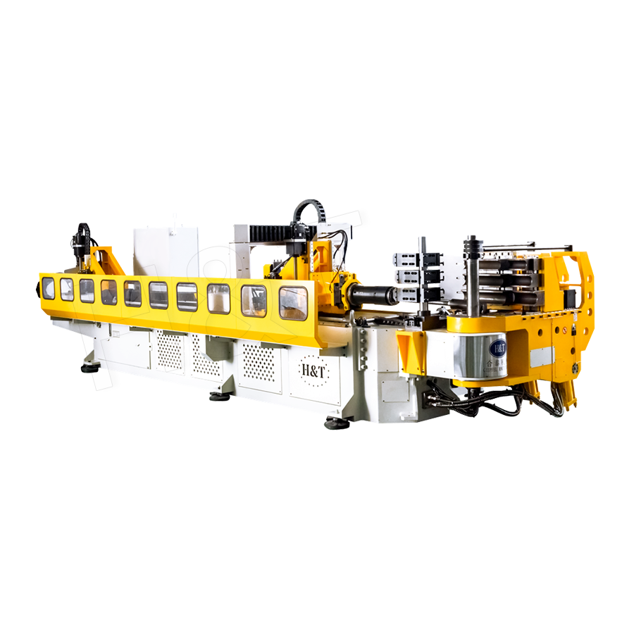
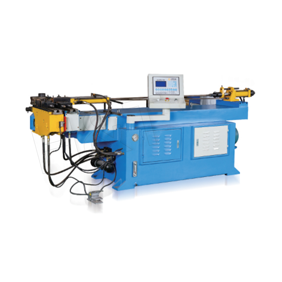
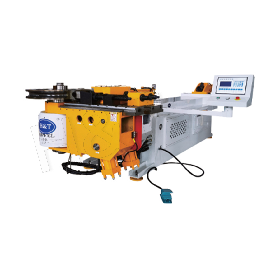
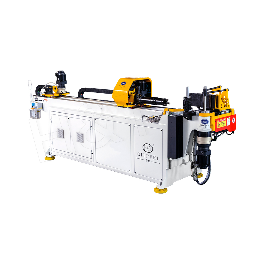
The CNC Bending machines in the pipe and profile forming series integrate all of these capabilities — closed-loop angle control, multi-axis simultaneous motion, springback compensation, and production data logging — into a production platform suitable for automotive, HVAC, furniture, medical equipment, and structural tube fabrication applications.
Springback: The Central Challenge That CNC Bending Solves Better Than Any Alternative
Springback — the elastic recovery of a bent part after the bending tool is removed — is the fundamental challenge in all metal bending processes. Every bending method must address it, but the quality and consistency with which springback is compensated is a key differentiator between CNC and non-CNC methods.
The Physics of Springback
When a metal tube is bent, the outer fibers of the cross-section are stretched (tensile stress) and the inner fibers are compressed. The material deforms plastically in the zones that exceed the yield stress, but elastic strain energy is stored throughout the bent zone — including in the plastically deformed regions. When the bending load is removed, this elastic energy causes the material to partially recover toward its original straight configuration: the bend angle decreases. The amount of springback depends on:
- Material yield strength — higher yield strength materials spring back more because a greater proportion of the deformation is elastic
- Elastic modulus (Young's modulus) — for a given yield strain, a higher elastic modulus produces more springback
- Bend radius relative to tube diameter — tighter radii (smaller bend radius to diameter ratio) produce less springback because a greater proportion of the cross-section deforms plastically
- Wall thickness — thinner walls have less elastic spring relative to the plastic zone depth and spring back proportionally less
Springback Variation Between Material Batches
Even when purchasing material from the same supplier to the same specification, yield strength variation between production batches is unavoidable. Typical mill certificates for structural steel tube specify yield strength to a range — for example, S275 steel has a specified minimum yield of 275 MPa but may actually have a yield strength anywhere from 275 MPa to 420 MPa depending on the specific heat and rolling parameters. This variation produces corresponding variation in springback — a batch at the high end of the yield range may spring back 2 to 3 degrees more than a batch at the low end for the same nominal bend angle, a difference that is immediately visible and often dimensionally unacceptable.
In manual and conventional hydraulic bending, this batch-to-batch variation requires the operator to produce test bends each time a new material batch is loaded and adjust the overbend setting manually. In CNC bending with closed-loop angle feedback, the system automatically detects the actual springback of each individual bend on the basis of the measured angle at full tooling engagement and adjusts the overbend dynamically — compensating for batch-to-batch variation within production without any manual intervention.
Springback in High-Strength and Advanced Materials
The challenge of springback is most severe in high-strength materials — advanced high-strength steel (AHSS) grades, titanium alloys, and precipitation-hardened stainless steels — where yield strengths of 600 MPa to over 1,500 MPa produce springback angles that may require overbending by 10 to 25 degrees or more to achieve a 90-degree final bend. Managing this in manual or conventional bending requires extensive empirical development of overbend tables and rigorous incoming material inspection. CNC bending with angular feedback manages it reliably through the control system, making CNC bending the enabling technology for precision bending of advanced high-strength materials in automotive body structures and aerospace components.
Multi-Stack Tooling and Right-Left Bending: Capabilities Unique to Advanced CNC Machines
Beyond the fundamental advantages in control precision and repeatability, advanced CNC bending machines offer tooling configuration options that are either impossible or highly impractical with non-CNC methods.
Multi-Stack Tooling
Some tube components require bends of different radii on the same part — for example, an automotive exhaust system that requires a tight-radius bend in a confined underbody section and a larger-radius sweep in an exposed section. Multi-stack CNC benders carry two to five complete sets of bend dies simultaneously on a common bend head. The CNC program specifies which die stack to engage for each bend in the sequence, and the machine rotates to the correct die automatically between bends. The entire complex part is produced in a single machine cycle without part re-fixturing. This capability has no manual or conventional bending equivalent — producing the same part by other means would require multiple separate bending operations on different machines with manual re-positioning between bends, multiplying the risk of cumulative dimensional error.
Right-Left Bending
Conventional rotary draw benders bend in one direction only — typically right-hand (clockwise when viewed from the material feed direction). Components with both right-hand and left-hand bends — such as S-bends or parts that reverse direction in three-dimensional space — would normally require the part to be removed, turned end-for-end, and rebent on a second setup. Right-left CNC bending machines carry both right-hand and left-hand bend head configurations and switch between them under program control. The result is that complex three-dimensional tube geometries requiring opposing bends can be completed in a single uninterrupted machine cycle, eliminating the re-fixturing error and handling damage risk of a two-setup process.
All-Electric CNC Bending
Contemporary CNC bending machines increasingly use all-electric servo drive systems rather than hydraulic power for all axes. All-electric CNC benders offer several advantages over hydraulic CNC machines:
- Higher positioning accuracy: Servo motor and ball-screw drive systems achieve positioning repeatability of plus or minus 0.01 mm or better, compared with plus or minus 0.05 to 0.1 mm for hydraulic systems with proportional valve control
- Faster cycle times: Electric servo axes accelerate and decelerate faster than hydraulic actuators, reducing inter-bend positioning time by 20 to 40% in multi-bend cycle applications (Source: International Journal of Advanced Manufacturing Technology, Guo et al., 2020)
- Lower energy consumption: Servo drives consume energy only when moving (regeneratively braking to recover energy during deceleration), whereas hydraulic systems maintain full pump pressure continuously. Energy savings of 30 to 60% per machine have been reported in production comparisons (Source: Journal of Cleaner Production, Joshi et al., 2019)
- Elimination of hydraulic oil: All-electric machines eliminate the fire risk, disposal cost, and maintenance requirement of hydraulic oil systems, which is significant in clean manufacturing environments such as medical device and food equipment tube fabrication
Industry Applications Where CNC Bending Is the Only Viable Method
In several industries, the quality, repeatability, and traceability requirements of tube and pipe components are such that CNC bending is not simply a preferred method but the only method capable of meeting specification.
Automotive Manufacturing
Modern automotive production operates on just-in-time delivery schedules with near-zero parts inventory. Every exhaust pipe, fuel line, brake pipe, air conditioning tube, and structural tube component must match the assembly fixture exactly — dimensional variation that requires manual adjustment at the assembly point disrupts the production line and is economically unacceptable. Automotive tube bending specifications typically require angular tolerances of plus or minus 0.3 to 0.5 degrees and linear tolerances of plus or minus 0.5 mm on finished parts, tolerances achievable in production only with CNC rotary draw bending. The automotive industry is the largest single user of CNC tube bending technology, accounting for approximately 45% of CNC bending machine installations globally (Source: Mordor Intelligence, CNC Bending Machine Market Report, 2022).
Aerospace and Defense
Hydraulic system tubing in aircraft must meet AS9100 quality management requirements and typically carries material traceability requirements linking every production record to the specific material heat and machine program used. The full production data logging capability of modern CNC bending machines — recording actual bend angle, actual rotation, cycle time, and operator ID for every bend on every part — provides this traceability without manual documentation. Aerospace hydraulic tube specifications commonly require angular tolerances of plus or minus 0.2 degrees and gap-from-nominal checks at assembly that are achievable only with CNC production.
Medical Equipment
Tubing components in medical devices — imaging equipment frames, surgical table structures, patient handling equipment — must be produced from verified-clean materials, bent without lubricants that could contaminate medical environments, and dimensionally verified against tight specifications. All-electric CNC bending machines operating without hydraulic oil are the appropriate production technology for this environment, and the full program traceability of CNC production supports the design history file documentation required by FDA 21 CFR Part 820 and ISO 13485.
HVAC and Refrigeration
Copper tube bending for HVAC evaporator and condenser coils requires the consistent tight-radius bends that only CNC mandrel bending can produce in thin-walled copper tube without ovality defects that would restrict refrigerant flow. High-speed CNC copper tube benders for HVAC coil production achieve cycle rates of up to 600 bends per hour on automated multi-head machines — production rates that manual or conventional bending cannot approach.
Choosing Between CNC Bending and Alternative Methods: A Decision Framework
Selecting the appropriate bending method for a given application requires evaluating several factors simultaneously. The table below provides a structured decision framework based on the most important selection criteria.
| Selection Factor | Favors CNC Bending | Favors Alternative Method |
|---|---|---|
| Production volume | Medium to high volume (50+ parts per production run) | Single prototype or very low volume (under 10 pieces) |
| Angular tolerance requirement | Tighter than plus or minus 1 degree | Looser than plus or minus 2 degrees |
| Number of bends per part | Two or more bends per part | Single simple bend |
| Tube outside diameter | 6 mm to 200 mm | Above 200 mm (induction or press bending); below 6 mm (hand forming) |
| Bend radius requirement | Tight radius (1 to 3 times OD) | Large radius (above 8 times OD) — roll bending; very large — induction |
| Cross-section ovality tolerance | Less than 3% ovality required | Ovality above 5% acceptable — press bending feasible |
| Material type | Carbon steel, stainless, aluminum, copper, titanium, AHSS | Very heavy wall carbon steel above 20 mm — induction preferred |
| Part-to-part traceability | Required (aerospace, medical, automotive) | Not required (general fabrication, site work) |
| Geometry complexity | Multi-plane, multi-radius, right-left bends | Single-plane, single-radius, simple geometry |
Featured Products
A Complete Range of Tube Processing Solutions
Precision Tube Bending
 Ready To Customise
Your Bent Tube Products?

Ready To Customise Your Bent Tube Products?
Proprietary software, smart control systems, and 50+ patents ensure more efficient and intelligent production at every step.
Copyright © 2025 by Gipfel Precision Machinery Co.,Ltd All Rights Reserved. Privacy Precision Tube Machinery Manufacturer | Pipe Forming, Cutting, End Forming Solutions
