

 简体中文
简体中文 English
 日本語
日本語 한국어
한국어 Español
 русский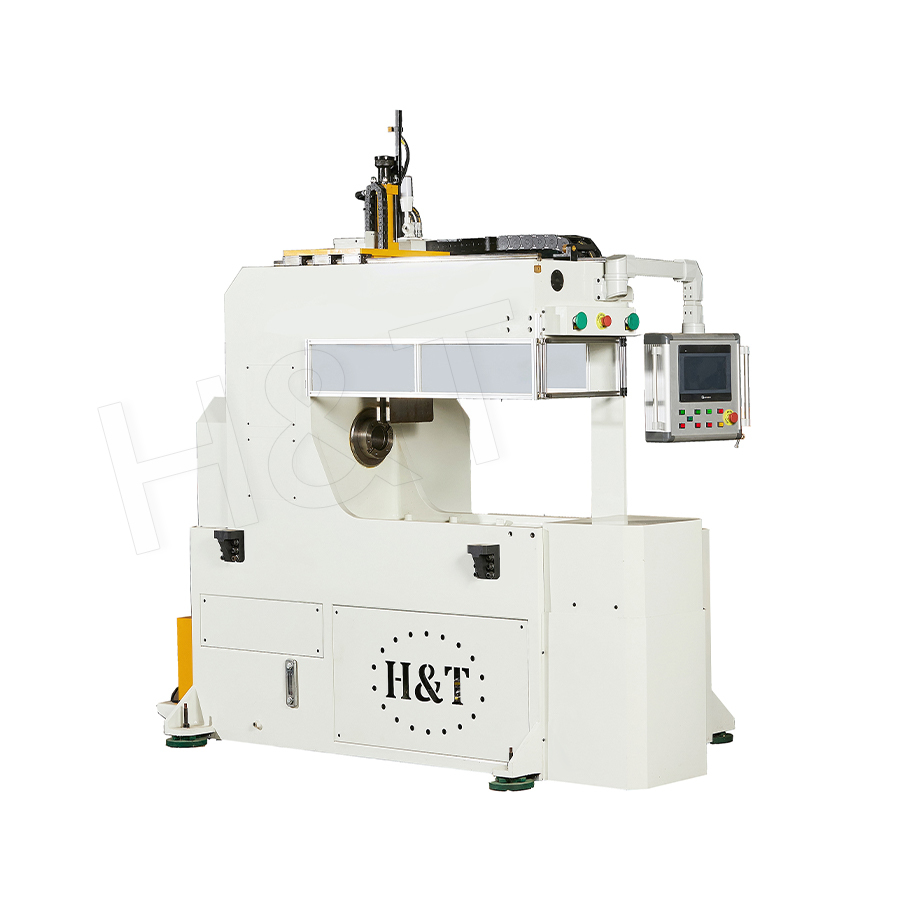
No. 196, Lifa Avenue, Haian City, Nantong, Jiangsu Province, China

News Category
Product Category
What are the uses of a Spiral Coil Bending?
Spiral Coil Bending is a metal forming process used to bend tube, pipe, or profile material into a continuous helical (spiral) shape with a fixed pitch and diameter, and it is primarily used to manufacture heat exchanger coils, cooling and refrigeration coils, structural helical piles, spiral staircases and railings, augers and screw conveyors, and decorative architectural elements. The process is valued because it produces a continuous, uniform helix from straight tube or bar stock without welding or joining multiple segments together, preserving material strength and eliminating the leak points or weak spots that a welded or segmented spiral would introduce.
Spiral coil bending machines achieve this by feeding straight tube, pipe, or profile material through a combination of guide rollers and a bending die or mandrel that progressively curves the material into a helix while simultaneously advancing it along the spiral axis -- controlling both the bend radius and the pitch (the axial distance between successive turns) independently and precisely. This dual control over radius and pitch is what distinguishes spiral coil bending from simple circular bending, and it is the capability that enables the wide range of industrial applications covered in this article.
Content
- 1 How Spiral Coil Bending Works
- 2 Heat Exchanger and Refrigeration Coils
- 3 Geothermal and Ground Source Heat Pump Loops
- 4 Structural and Foundation Applications: Helical Piles and Anchors
- 5 Augers and Screw Conveyors
- 6 Architectural and Decorative Applications
- 7 Springs and Coil Products
- 8 Industrial Process Equipment: Coil Tubing and Process Coils
- 9 Application Comparison: Spiral Coil Geometry by Industry
- 10 Why Spiral Coil Bending Is Preferred Over Alternative Methods
- 11 Selecting Spiral Coil Bending Equipment for Industrial Production
How Spiral Coil Bending Works
Understanding the mechanics of the spiral coil bending process clarifies why it is suited to such a diverse set of applications, and what technical parameters determine whether a given application is achievable on a given machine.
Radius and Pitch Control
A spiral coil bending machine controls two independent geometric parameters: the bend radius (the diameter of the resulting helix) and the pitch (the axial distance the helix advances per revolution). These two parameters are controlled independently through the bending die geometry and the axial feed rate of the material, allowing the same machine to produce tightly wound coils with minimal pitch -- as used in heat exchanger coils -- or widely spaced helixes with large pitch -- as used in augers or helical piles -- from the same base equipment with different tooling and feed settings.
Material Compatibility
Spiral coil bending is applicable to a wide range of materials including carbon steel, stainless steel, copper, aluminum, and titanium tube and pipe, as well as solid round bar and structural angle or flat profile stock. Tube diameters commonly processed range from 6 mm to over 150 mm, with wall thickness and material yield strength both influencing the minimum achievable bend radius without wall collapse or excessive ovality at the bend.
Mandrel and Support Tooling
For thin-wall tube, particularly in heat exchanger and refrigeration coil applications, an internal mandrel or wiper die is used during bending to prevent the tube wall from collapsing or wrinkling on the inside of the bend radius. The mandrel supports the tube wall from the inside while the bending die applies the forming force from the outside, maintaining a round cross-section through the bend and preserving the internal flow area required for the tube's function as a fluid-carrying conduit.

Heat Exchanger and Refrigeration Coils
The single largest application of spiral coil bending by production volume is the manufacture of coils for heat exchangers, refrigeration systems, and air conditioning equipment. A spiral or helical coil maximizes the heat transfer surface area within a compact installed volume -- a critical design objective for evaporator coils, condenser coils, and water heating coils used across HVAC and refrigeration industries.
Copper and aluminum tube spiral coils are the standard heat exchanger element in residential and commercial air conditioning condenser units, with typical tube diameters of 9.52 mm (3/8 inch) to 15.88 mm (5/8 inch) formed into multi-turn helical coils with pitch spacing of 20 to 35 mm between turns, depending on the airflow design and fin spacing of the heat exchanger assembly. According to the Air-Conditioning, Heating, and Refrigeration Institute (AHRI, ahrinet.org), coil geometry -- including bend radius consistency and pitch uniformity -- directly affects refrigerant pressure drop and heat transfer coefficient, making precise spiral bending a determining factor in overall system energy efficiency ratings.
Industrial process heat exchangers -- used in chemical processing, oil and gas, and power generation -- frequently use stainless steel or carbon steel spiral coils of larger diameter, from 25 mm to 100 mm, wound into helical coil bundles installed within shell-and-tube or coil-in-shell heat exchanger vessels. These coils must maintain dimensional consistency across the full coil length to ensure uniform fit within the shell housing and consistent flow distribution across all coil passes.
Geothermal and Ground Source Heat Pump Loops
Geothermal heating and cooling systems rely on buried ground loop heat exchangers to transfer thermal energy between a building and the stable temperature of the earth. Spiral or "slinky" coil configurations are one of the two standard horizontal ground loop geometries used in these systems, alongside straight horizontal loops, and are specifically chosen when available trench length is limited relative to the required heat exchange surface area.
A spiral ground loop coil is formed by bending high-density polyethylene (HDPE) pipe -- typically 19 mm to 32 mm (3/4 inch to 1.25 inch) diameter -- into a continuous helix with a coil diameter of 0.5 to 1.0 meters and pitch spacing of 150 to 300 mm, which is then laid horizontally within a trench. This configuration achieves 3 to 5 times more pipe length per linear meter of trench compared to a straight horizontal loop of the same trench length, according to the International Ground Source Heat Pump Association (IGSHPA, igshpa.org), substantially reducing the land area or trench excavation required for a given heating and cooling capacity.
The consistent pitch and radius achievable through dedicated spiral coil bending equipment ensures that ground loop coils maintain uniform pipe spacing throughout their length, which is important for achieving the predicted thermal performance modeled during geothermal system design -- inconsistent coil spacing creates localized hot or cold zones in the surrounding soil that reduce overall heat exchange efficiency.
Structural and Foundation Applications: Helical Piles and Anchors
Helical piles -- also called screw piles or helical anchors -- are deep foundation elements consisting of a steel shaft with one or more helical plates welded along its length, installed by rotating the pile into the ground much like a large screw. While the helical plates themselves are typically formed from flat steel plate rather than bent tube, the manufacturing process for the helical lead sections of certain helical pile and ground anchor designs uses spiral bending of bar or profile stock to form continuous helical flighting that is then welded to the central shaft.
Helical piles are widely used for foundation support in soft or variable soil conditions, for solar farm racking foundations, for boardwalk and pier construction, and for retrofit foundation underpinning where access for conventional pile driving equipment is restricted. The helical flight geometry -- pitch, diameter, and number of helix turns -- is engineered to the specific soil bearing capacity and design load requirements at each site, and is calculated according to standards such as ICC-ES AC358 (Acceptance Criteria for Helical Pile Systems) in North America.
Augers and Screw Conveyors
Helical screw flighting is the functional core of every screw conveyor and auger system used across agriculture, food processing, bulk materials handling, and construction equipment industries. Spiral coil bending of flat strip or bar stock into a continuous helical flight is one of the primary manufacturing methods for producing this flighting, particularly for sectional or formed-flight augers where a continuous helix is bent directly from strip stock rather than cut from flat plate.
Auger flighting produced by spiral bending is used in grain handling and storage equipment, where screw conveyors move grain horizontally or vertically between storage silos, processing equipment, and transport vehicles. The Conveyor Equipment Manufacturers Association (CEMA, cemanet.org) publishes standard flighting dimensions and pitch-to-diameter ratios for screw conveyor design -- typical pitch is set equal to the conveyor diameter (a 1:1 pitch-to-diameter ratio) for general bulk material handling, though pitch can be reduced to 0.5:1 for inclined or vertical conveying applications requiring greater material control.
Construction and drilling augers -- used for post hole digging, foundation drilling, and earth boring equipment -- similarly rely on helical flighting formed by spiral bending, sized and pitched according to the soil type and torque characteristics of the drilling equipment. Concrete pump auger components and continuous flight auger (CFA) piling rigs both use spiral-formed flighting manufactured to demanding dimensional tolerances to ensure consistent material displacement during drilling.
Architectural and Decorative Applications
Spiral coil bending is widely used in architectural metalwork to produce structural and decorative helical components that would be extremely difficult or impossible to achieve through alternative fabrication methods such as segmented welding.
Spiral Staircases and Stringers
The structural stringer of a spiral staircase -- the helical beam that supports the treads -- is frequently formed from tube or structural profile using spiral bending to achieve a continuous, smooth helical curve without the visible joints and potential weak points that a segmented, welded stringer would introduce. A continuous spiral-bent stringer also distributes structural load more evenly along its length, as the helix geometry itself contributes to the stiffness of the structure under both vertical and torsional loading from stair use.
Handrails and Balustrades
Helical handrails that follow the curve of a spiral staircase, curved ramp, or architectural feature require continuous tube bent to match the precise radius and rise (vertical pitch) of the underlying structure. Spiral coil bending equipment capable of producing a three-dimensional helix -- combining both horizontal curvature and vertical rise simultaneously -- is the standard production method for handrail manufacturers serving architectural and commercial construction projects, where a smooth, continuous, joint-free rail is both a safety requirement and an aesthetic expectation.
Decorative Sculptural and Facade Elements
Architectural facade screens, decorative columns, sculptural installations, and feature lighting structures increasingly incorporate spiral-formed tube and bar elements as a distinctive design feature. The precision and repeatability of modern spiral coil bending equipment allows architectural fabricators to produce multiple identical helical elements for facade systems or installations requiring consistent geometry across many repeated units -- a requirement that manual or improvised bending methods cannot reliably achieve at architectural project scale.
Springs and Coil Products
While dedicated spring coiling machines are used for high-volume precision compression and tension spring manufacturing, spiral coil bending technology is used for larger-diameter, larger-pitch helical coil products that fall outside the typical spring coiling machine range -- including large industrial springs, coil-wound structural dampers, and helical coil reinforcement used in certain composite and concrete construction applications.
Helical coil reinforcement -- continuous spiral-formed reinforcing bar used to confine concrete columns and piles -- is a structural application where consistent pitch and diameter directly affect the confinement performance and seismic resistance of the reinforced concrete element. Standards such as ACI 318 (Building Code Requirements for Structural Concrete) specify minimum spiral reinforcement pitch and bar diameter requirements based on the column design load and seismic design category, making dimensional accuracy in the spiral bending process directly relevant to structural code compliance.
Industrial Process Equipment: Coil Tubing and Process Coils
Beyond heat exchangers, spiral-formed tube coils are used in a range of industrial process applications where a compact, high-surface-area tube configuration is required within process vessels, tanks, or reactors.
- Tank heating and cooling coils: Spiral coils submerged within storage tanks, mixing vessels, or fermentation tanks provide indirect heating or cooling of the tank contents via a heat transfer fluid circulated through the coil, without direct contact between the process fluid and an external heat source.
- Pasteurization and sterilization coils: Food and beverage processing equipment uses precisely formed spiral tube coils to achieve the specific residence time and heat transfer rate required for pasteurization or sterilization processes, with coil length, diameter, and pitch all calculated to deliver the target thermal treatment as product flows through the coil.
- Oil and gas coiled tubing applications: While downhole coiled tubing for well intervention is manufactured by specialized continuous mill processes rather than discrete spiral bending, surface process coils used in oilfield separator and heater-treater equipment commonly use spiral-bent tube coils for the same heat transfer functions found in other process industries.
- Solar thermal collector coils: Solar water heating systems use spiral-formed copper or stainless steel coils as the heat exchanger element within the solar storage tank, transferring heat collected by the solar thermal panel circuit into the domestic hot water supply without mixing the two fluid circuits.
Application Comparison: Spiral Coil Geometry by Industry
The table below summarizes the typical geometric parameters and material types used in spiral coil bending across the principal application industries, illustrating the versatility of the process across vastly different scales and performance requirements.
| Application | Typical Material | Tube/Bar Diameter Range | Pitch Characteristic | Governing Standard |
|---|---|---|---|---|
| HVAC and refrigeration coils | Copper, aluminum | 6 to 16 mm | Tight pitch (20 to 35 mm) | AHRI standards |
| Geothermal ground loops | HDPE pipe | 19 to 32 mm | Medium pitch (150 to 300 mm) | IGSHPA guidelines |
| Helical pile flighting | Carbon steel | Plate-formed; varies by design | Single to multi-turn helix | ICC-ES AC358 |
| Screw conveyors and augers | Carbon steel, stainless steel | Strip-formed; diameter varies | 0.5:1 to 1:1 pitch-to-diameter | CEMA standards |
| Spiral staircase stringers | Carbon steel, stainless steel | 50 to 150 mm tube/profile | Wide pitch matched to stair rise | Local building codes |
| Process and tank coils | Stainless steel, carbon steel | 25 to 100 mm | Application-specific | ASME process design codes |
| Spiral concrete reinforcement | Reinforcing steel bar | 6 to 16 mm bar | Tight, code-specified pitch | ACI 318 |
Why Spiral Coil Bending Is Preferred Over Alternative Methods
Several alternative manufacturing approaches could theoretically produce a helical shape -- including segmented welding of multiple curved sections, casting, or manual hand-forming -- but spiral coil bending offers specific advantages that explain its dominance across the application areas described above.
- Material continuity and structural integrity: A continuously bent spiral has no welds or joints along its helical length, eliminating the stress concentration points, potential leak paths, and corrosion-initiation sites that welded joints introduce. For pressure-containing applications such as heat exchanger coils, this continuity is essential to long-term reliability.
- Dimensional consistency across production runs: Machine-controlled spiral bending produces highly repeatable pitch and radius across the full coil length and across multiple production units, which is essential for applications where coils must fit within fixed housings or vessels, or where multiple identical units must be produced for an architectural or industrial installation.
- Reduced material waste and labor cost: Forming a spiral from continuous straight stock avoids the material waste and labor-intensive welding and finishing work associated with segmented or cast alternatives, improving production efficiency for both small-batch and high-volume manufacturing.
- Capability across diverse materials and scales: The same fundamental bending principle, with appropriate tooling, scales from small-diameter copper refrigeration tube to large-diameter structural steel tube used in architectural stringers -- giving manufacturers a single process platform capable of serving multiple product lines and industries.
Selecting Spiral Coil Bending Equipment for Industrial Production
Manufacturers evaluating spiral coil bending equipment for production use should assess machine capability against the specific diameter range, pitch range, material type, and production volume requirements of their target applications. Key technical specifications to evaluate include the maximum and minimum tube or bar diameter the machine can process, the achievable pitch range and adjustment precision, the maximum material yield strength the bending mechanism can form without excessive springback or tooling wear, and the level of automation available for pitch and diameter changeover between different production batches.
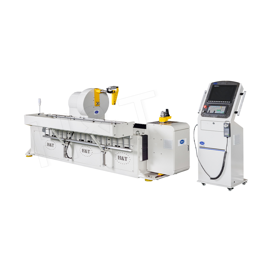
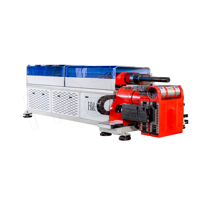
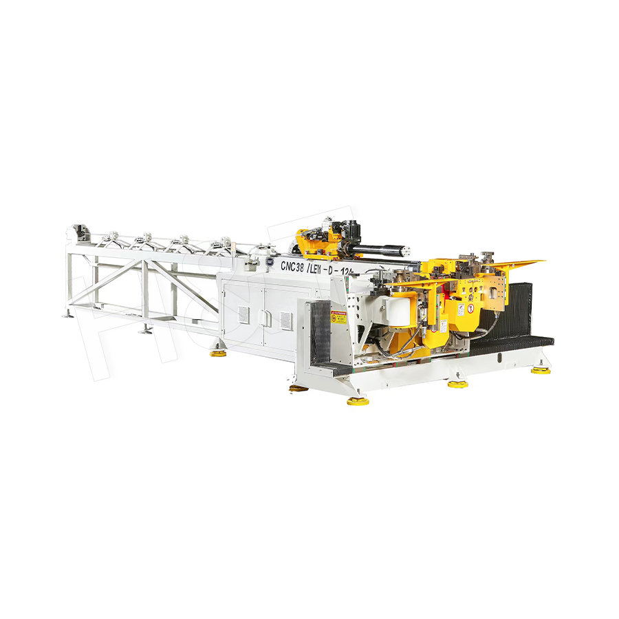
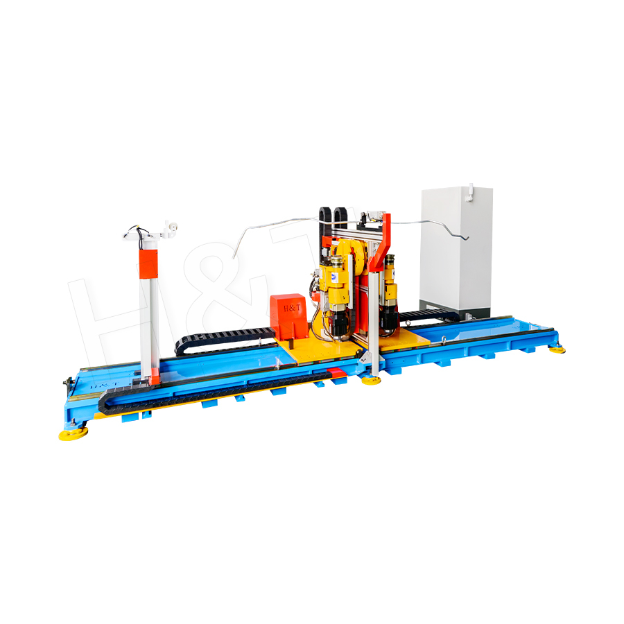
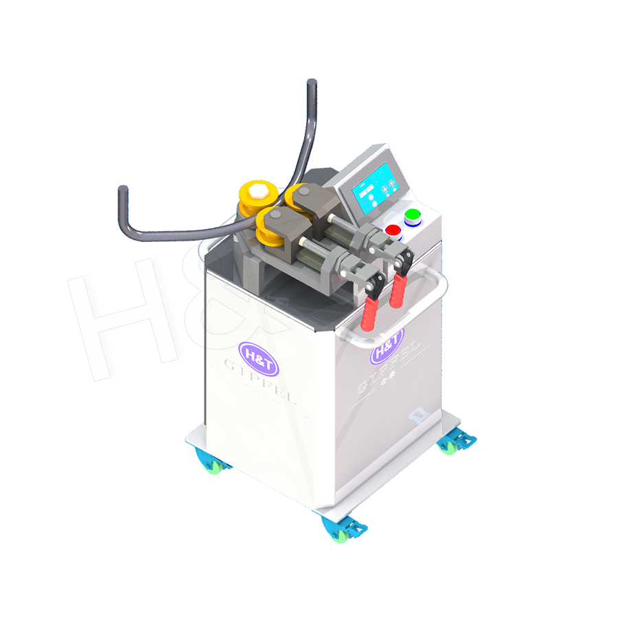
For manufacturers serving multiple industries from heat exchanger coils to architectural stringers, equipment with a wide processing range and rapid tooling changeover capability provides the flexibility to serve diverse customer requirements from a single production asset. The Spiral Coil Bending equipment within the pipe and profile forming product range is engineered to deliver the diameter range, pitch control precision, and changeover flexibility required to support production across these varied application areas, from precision HVAC coil manufacturing through to larger-diameter structural and architectural spiral forming work.
Featured Products
A Complete Range of Tube Processing Solutions
Precision Tube Bending
 Ready To Customise
Your Bent Tube Products?

Ready To Customise Your Bent Tube Products?
Proprietary software, smart control systems, and 50+ patents ensure more efficient and intelligent production at every step.
Copyright © 2025 by Gipfel Precision Machinery Co.,Ltd All Rights Reserved. Privacy Precision Tube Machinery Manufacturer | Pipe Forming, Cutting, End Forming Solutions
