 English
 日本語
日本語 한국어
한국어 Español
 русский
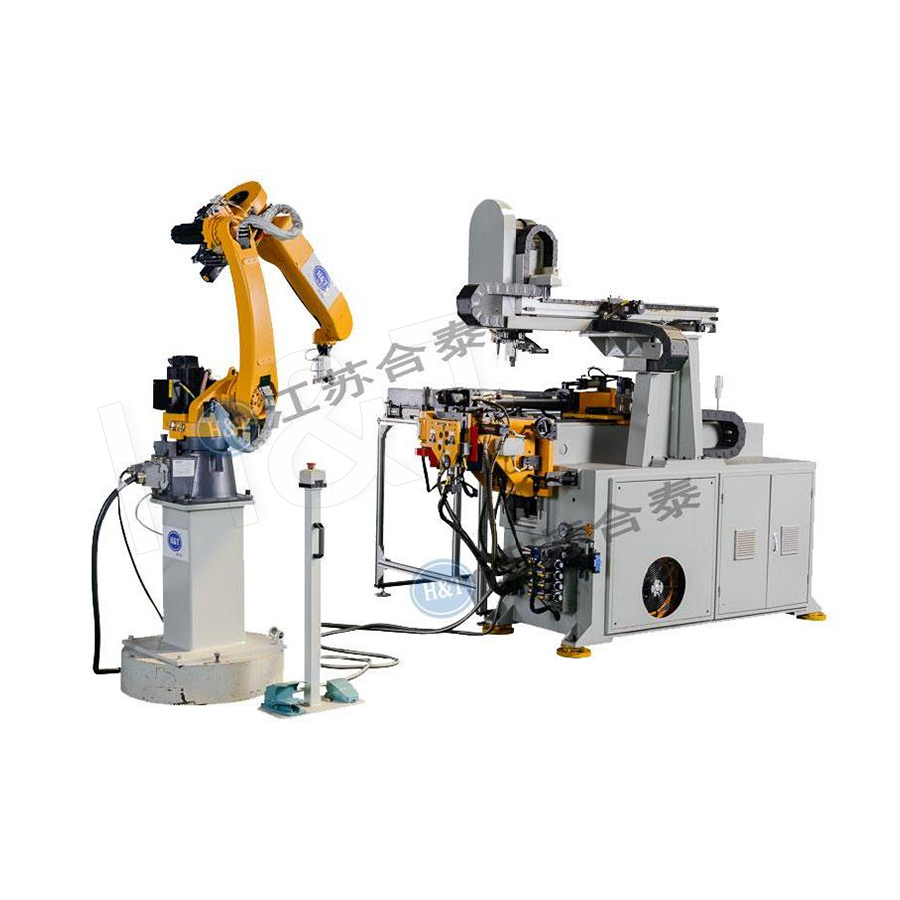
No. 196, Lifa Avenue, Haian City, Nantong, Jiangsu Province, China
News Category
Product Category
What is Robot tube Bending?
Robot tube bending is the deep integration of industrial robotic arms with CNC (Computer Numerical Control) tube bending machines to form a fully automated system capable of automatically feeding, positioning, clamping, bending, and unloading tubes without manual intervention. The robot handles the tube — gripping, orienting, and repositioning it with high precision — while the CNC bending machine performs the actual forming operation using preset dies and pressure tooling to achieve the required bending angle, radius, and three-dimensional geometry.
In practice, robot tube bending transforms traditional manual or semi-automatic tube bending operations into fully automated production cells. The industrial robot's flexible multi-axis motion — typically 6 degrees of freedom — allows it to handle tubes of varying diameters, wall thicknesses, and lengths, reposition them between successive bends, and adapt to complex multi-plane geometries that would be extremely difficult or impossible to achieve consistently through manual handling. The system supports quick fixture changes, parallel multi-mold installations, and programmable execution of multiple bending shapes in sequence, making it the cornerstone of high-volume, high-precision tube fabrication in automotive, aerospace, HVAC, medical equipment, and structural manufacturing industries.
Content
- 1 How Robot Tube Bending Works: The Complete Process
- 2 Key Components of a Robot Tube Bending System
- 3 The Industrial Robot's Role: Multi-Axis Flexibility as the Key Enabler
- 4 Types of Bending Methods Used in Robot Tube Bending Systems
- 5 Key Advantages of Robot Tube Bending Over Manual and Semi-Automatic Methods
- 6 Industries That Rely on Robot Tube Bending
- 7 Robot Tube Bending vs Conventional CNC Tube Bending: Key Differences
- 8 Programming and Software in Robot Tube Bending Systems
- 9 Tube Materials and Diameters Compatible With Robot Tube Bending
- 10 Quality Control and Inspection in Robot Tube Bending
- 11 Economic Justification: When Robot Tube Bending Makes Financial Sense
How Robot Tube Bending Works: The Complete Process
Understanding what robot tube bending is requires understanding how the robotic and bending machine systems interact throughout the complete tube processing cycle. The process integrates hardware (robot, bending machine, tooling, conveyors) and software (robot programs, CNC bending programs, synchronization control) into a seamless automated workflow.
Step 1: Automated Tube Feeding and Loading
Raw tube stock — typically in straight lengths of 3 to 6 meters — is loaded onto a feed conveyor, bundle rack, or magazine system adjacent to the robot work cell. The industrial robot uses a purpose-designed end-of-arm tool (EOAT) — a gripper or chuck configured for the specific tube diameter — to pick up individual tubes from the feed station. Vision systems or mechanical stop sensors confirm tube position before the robot grips, ensuring that each tube is picked correctly regardless of minor variations in feed position.
Step 2: Tube Positioning and Initial Clamping
The robot carries the tube to the bending machine and positions it precisely within the machine's clamping and bending toolset. The tube is located against reference stops or within a collet chuck to establish the correct insertion depth and rotational orientation for the first bend. The bending machine clamps the tube securely — the pressure die, bend die, and wiper die close around the tube — and the robot releases its grip or maintains a controlled supporting position while the first bend is executed.
Step 3: CNC-Controlled Bending
With the tube clamped in the bending machine toolset, the CNC system executes the bending operation — rotating the bend die around a defined center to pull the tube around the bending radius to the specified angle. The bending program accounts for the material's springback behavior, pre-programming a slight overbend that, after the tooling releases, returns the tube to the exact specified angle. Modern CNC tube benders control bend angle to tolerances of ±0.1° and bend position (YBC values — feed length Y, bend angle B, and rotation C) to within ±0.2 mm, delivering the geometric precision that complex tube assemblies require.
Step 4: Robot Repositioning Between Bends
After each bend is completed, the bending machine releases the tube and the robot — or the machine's own tube feed axis — repositions the tube for the next bend. This repositioning involves advancing the tube by the correct feed length (Y-axis), rotating it to the correct angular position about its own axis (C-axis), and verifying that the previously bent portion of the tube clears the machine structure and toolset as the tube is repositioned. The robot's six-axis dexterity allows it to maneuver tubes with previously bent sections around the bending machine's geometry — a critical capability for complex multi-plane tube shapes.
Step 5: Unloading and Part Transfer
Once all bends in the program are complete, the robot picks up the finished bent tube assembly and transfers it to an unloading conveyor, part rack, or directly to the next processing station (welding, deburring, inspection). The finished part is confirmed against quality checkpoints — either inline with a 3D vision system or periodically with a coordinate measuring machine — and the cycle restarts with the next tube blank.

Key Components of a Robot Tube Bending System
A complete robot tube bending cell integrates several major subsystems that must work in coordinated synchronization to achieve fully automated, high-precision tube forming. Each component plays a specific and essential role in the system's overall capability.
| Component | Function | Key Specification |
|---|---|---|
| Industrial Robot Arm | Gripping, positioning, and transferring tubes between stations | 6-axis, payload 50–500 kg, reach 1.5–3.5 m |
| CNC Tube Bending Machine | Executing precise bend operations using programmed YBC values | Bend angle ±0.1°, tube OD range 6–220 mm |
| End-of-Arm Tooling (EOAT) | Gripping the tube securely without surface damage | Quick-change design for multi-diameter capability |
| Bend Die, Pressure Die, Wiper Die | Forming the tube around the specified bend radius | Material-matched, radius-specific tooling sets |
| Tube Feed Conveyor / Magazine | Supplying straight tube stock to the robot pick-up station | Capacity for continuous multi-shift operation |
| Robot Controller | Executing robot motion programs and coordinating with CNC machine | Real-time synchronization with bending machine PLC |
| Vision / Sensor System | Confirming tube position, detecting feeding errors, quality inspection | 2D/3D camera systems, laser line scanners |
| CAD/CAM Offline Programming Software | Generating robot and bending programs from 3D tube models | Springback compensation, collision simulation |
The Industrial Robot's Role: Multi-Axis Flexibility as the Key Enabler
The industrial robot is the element that fundamentally distinguishes robot tube bending from conventional automated tube bending. While a standard CNC tube bender automates the bending motion itself, it still relies on mechanical tube feed axes with limited flexibility for tube positioning. The integration of a 6-axis industrial robot replaces and dramatically extends this capability.
Six Degrees of Freedom for Unlimited Tube Geometry
A 6-axis industrial robot arm can move its end effector (gripper) to any point within its working envelope with any orientation — a capability that translates directly into the ability to present a tube to the bending machine at any required position and angle. This is critical for complex multi-plane tube shapes where successive bends occur at different rotational orientations, and where the growing bent section of the tube must be maneuvered around the bending machine structure without collision.
For tubes with 5 or more bends in complex three-dimensional geometries — such as automotive fuel line assemblies, hydraulic brake tubes, or HVAC manifold tubes — the robot's six-axis flexibility is not just convenient but essential. The robot's offline programming software simulates the complete bending sequence including collision checking, optimizing the robot's path between each bend to ensure the bent tube clears all obstacles without manual intervention or machine downtime for path correction.
Quick Fixture Change for Multi-Product Flexibility
Robot tube bending systems can quickly change fixtures — the end-of-arm grippers and the bending machine's tooling sets — to process tubes of different diameters, wall thicknesses, and bending radii. Automatic tool changers on the robot's wrist allow end-of-arm tooling (EOAT) changes in under 60 seconds; bending machine tooling changes are similarly accelerated by quick-release die mounting systems. This rapid changeover capability means that a single robot tube bending cell can process 10, 20, or more different tube part numbers per shift — a flexibility that a dedicated hard-tooled machine cannot approach.
Adjustable Gripping Position to Accommodate Length Variation
The robot can adjust its gripping position along the tube's length to optimize the leverage for each bend, minimize overhang that could cause tube deflection during forming, and avoid gripping on a previously bent section that would prevent the tube from being presented correctly to the bending machine. This intelligent grip position adjustment — programmed in the robot's offline software — is a subtle but important capability that significantly improves bending accuracy on long or complex parts.
Types of Bending Methods Used in Robot Tube Bending Systems
Robot tube bending systems are not limited to a single bending method — the robot can be integrated with different bending machine types to achieve different forming characteristics suited to specific material, geometry, and quality requirements.
Rotary Draw Bending (RDB)
The most common and precise bending method in robot tube bending systems. The tube is clamped to a rotating bend die and drawn around it as the die rotates, guided by a pressure die that supports the outside of the bend and an optional mandrel inside the tube that prevents wall collapse. Rotary draw bending achieves tight bend radii (as tight as 1× tube diameter in some applications) with minimal wall thinning and excellent cross-section preservation. It is the standard method for precision tube bending in automotive, aerospace, and medical device applications, capable of bending tube diameters from 4 mm to over 200 mm depending on machine capacity.
Compression Bending
In compression bending, the tube is held against a fixed bend die and a sliding pressure die pushes the tube around the die. This simpler and lower-cost method is suitable for mild steel and aluminum tubes in applications where tight tolerances and thin walls are not required. Robot integration with compression bending machines is common in general fabrication and structural applications where throughput and flexibility are more important than dimensional precision.
Roll Bending
Roll bending uses three or more rolls to progressively form large-radius bends in tubes, profiles, and sections. Robot integration with roll benders allows continuous feeding and repositioning of long tube or section lengths through the rolls, enabling complex helical or spiral geometries and large-radius architectural tube curves. Applications include handrails, structural curved members, and large-diameter piping systems.
Push Bending and Free-Form Bending
In push bending — also called free-form or 3D free bending — the robot itself performs both the feeding and the bending by pushing the tube through a moving bending die or guide nozzle while controlling the tube's spatial path. This approach allows creation of continuously varying radius bends (as opposed to discrete constant-radius bends) and very complex 3D geometries without the need for dedicated form-specific tooling. Push bending systems are particularly valued for prototyping and for complex architectural and automotive exhaust geometry applications.
Key Advantages of Robot Tube Bending Over Manual and Semi-Automatic Methods
The adoption of robot tube bending systems across high-volume manufacturing is driven by a set of well-documented performance advantages over manual bending and conventional semi-automatic CNC bending without robot integration.
- Repeatability and accuracy: Industrial robots repeat programmed positions with repeatability of ±0.05 mm or better (ISO 9283 standard). Combined with CNC bending machine precision, robot tube bending achieves consistent bend angle accuracy of ±0.1° and positional accuracy of ±0.2 mm part-to-part — far beyond what manual handling can sustain across a full production shift.
- Throughput and production speed: Robot systems operate continuously without fatigue, breaks, or shift changes. A robot bending cell running three shifts per day achieves 3× the effective production time of a single-shift manual operation with no increase in labor cost per additional shift, dramatically reducing cost per bent part at volume.
- Elimination of operator fatigue-related defects: Manual tube bending quality degrades as operators tire — grip consistency, loading position, and reaction speed all vary through a long production shift. Robot systems maintain identical performance at hour 1 and hour 10 of a shift, eliminating the end-of-shift quality degradation that generates scrap and rework in manual operations.
- Handling of complex multi-plane geometries: Manual handling of complex 3D tube shapes — particularly those with many closely spaced bends in multiple planes — requires exceptional operator skill and is extremely error-prone. The robot's programmed motion handles these geometries reliably and consistently from the first part.
- Improved worker safety: Tube handling is physically demanding and carries risks of cuts from tube ends, crush injuries from bending machine tooling, and ergonomic injuries from repetitive heavy lifting. Robot automation removes operators from direct contact with the bending process, significantly reducing injury rates in tube fabrication operations.
- Reduced scrap and material waste: The combination of precise robot positioning and accurate CNC bending reduces first-article failure rates and in-process scrap. Studies in automotive tube fabrication have shown that robot bending cells typically achieve scrap rates below 0.5% compared to 3–8% for manual or semi-automatic operations on complex parts.
- Multi-product flexibility through reprogramming: Changing to a different tube part requires only a program recall and (if necessary) a tooling change — a process achievable in minutes. The same robot cell that bends automotive fuel lines can be reprogrammed to bend HVAC refrigerant tubes or structural handrail components without capital investment in additional dedicated equipment.
Industries That Rely on Robot Tube Bending
Robot tube bending is a critical manufacturing technology in any industry that uses bent tube assemblies in its products. The combination of precision, repeatability, and flexibility makes it indispensable in industries where tube geometry directly affects product performance, safety, or cost.
Automotive Manufacturing
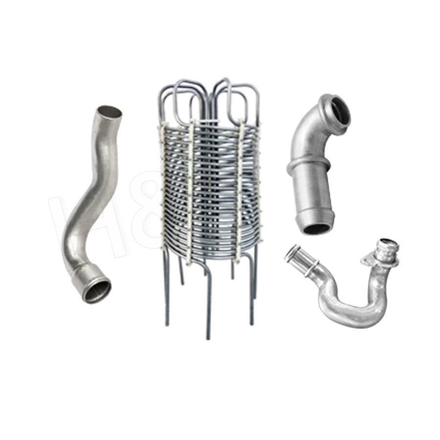
The automotive industry is the largest single user of robot tube bending technology. A typical passenger vehicle contains over 100 individual bent tube components — including fuel delivery lines, brake hydraulic tubes, exhaust systems, air conditioning refrigerant lines, power steering lines, engine coolant pipes, and chassis structural tubes. Each of these requires consistent geometry to fit within tight vehicle packaging constraints and to meet safety and performance requirements. Robot tube bending cells in automotive Tier 1 suppliers commonly achieve cycle times of 15 to 40 seconds per part, operating continuously across three-shift production schedules to support just-in-time delivery requirements.
Aerospace and Defense
Aerospace applications demand the highest dimensional accuracy and quality documentation of any tube bending application. Hydraulic system tubes, pneumatic lines, fuel system tubes, and environmental control system ducting in aircraft must meet tolerances often tighter than ±0.5 mm on all geometry parameters, with full material traceability and inspection documentation for every part. Robot bending systems integrated with 3D coordinate measurement and inspection equipment provide the combination of precision bending and documented quality assurance that aerospace certification requires.
HVAC and Refrigeration
HVAC manufacturers produce large volumes of copper and aluminum refrigerant tubes, heat exchanger connections, and air handling system components that require consistent bend geometry for correct assembly and leak-free joint formation. Robot bending cells in HVAC manufacturing typically process high volumes of relatively simple 2D tube geometries at high speed — optimizing for throughput and low scrap rate rather than geometric complexity — making them ideal for lights-out manufacturing environments.
Medical Devices and Equipment
Medical equipment — from patient beds and wheelchair frames to surgical instrument tables and imaging equipment structures — requires structural tube assemblies with consistent geometry for correct assembly, reliable function, and regulatory compliance. Small-diameter stainless steel tube bending for endoscope components, catheter manufacturing equipment, and surgical instrument handles demands the high precision and clean-room compatible processing that robot bending systems can provide with appropriate contamination controls.
Furniture, Fitness Equipment, and Consumer Goods
Steel and aluminum tube bending for furniture frames, bicycle frames, gym equipment, baby strollers, and shopping carts represents a high-volume application where robot bending's combination of speed, consistency, and quick changeover between product models delivers strong competitive advantage. The wide variety of product geometries and frequent model changes in these markets particularly benefit from the robot system's reprogrammability.
Robot Tube Bending vs Conventional CNC Tube Bending: Key Differences
To understand what robot tube bending uniquely offers, it is useful to compare it directly with conventional CNC tube bending — the automated but non-robotic approach it builds upon and extends.
| Capability | Robot Tube Bending | Conventional CNC Tube Bending |
|---|---|---|
| Loading / unloading | Fully automated by robot | Manual operator required |
| Complex 3D multi-bend handling | Excellent — 6-axis robot maneuvers bent sections | Limited — machine Y-B-C axes only |
| Multi-product flexibility | Very high — program recall + quick tooling change | Moderate — program change, manual tooling change |
| Unattended / lights-out operation | Yes — with adequate tube magazine capacity | No — operator presence required |
| Handling of long tube blanks | Excellent — robot supports and controls whole tube | Difficult — outboard support required |
| Integration with inspection systems | Straightforward — robot transfers parts to inspection | Manual inspection required |
| Initial investment cost | Higher (robot + integration + programming) | Lower (machine only + operator labor) |
| Operating labor cost | Very low — one operator can supervise multiple cells | Higher — dedicated operator per machine |
Programming and Software in Robot Tube Bending Systems
The intelligence of a robot tube bending system resides largely in its programming and software architecture. Modern systems use a hierarchy of software layers that together translate a 3D tube design into a running production program with minimal manual intervention.
CAD/CAM Offline Programming
Offline programming (OLP) software receives the 3D tube design from the product CAD system and automatically generates both the CNC bending machine program (YBC bend sequence with springback compensation) and the robot motion program (pickup, positioning, inter-bend repositioning, unloading paths). The software simulates the complete bending sequence virtually — including collision detection between the bent tube, the robot arm, and the bending machine structure — and optimizes robot paths to eliminate collisions before the program runs on the physical system. This virtual commissioning approach dramatically reduces physical setup time and eliminates the trial-and-error programming that was previously required for complex new parts.
Springback Compensation Algorithms
All metallic tube materials spring back elastically after the bending tooling is released — the tube's bent angle increases slightly as the elastic strain component recovers. The magnitude of springback depends on the material's yield strength, Young's modulus, tube wall thickness, and bend radius. Advanced bending software incorporates material-specific springback models that pre-compensate the programmed bend angle so that the tube's final angle after springback matches the specified design angle. Modern springback compensation algorithms achieve final bend angle accuracies of ±0.1° to ±0.3° without requiring manual trial-and-error adjustment on the first part.
Robot-Machine Synchronization and Safety Control
The robot controller and the bending machine CNC communicate in real time through a fieldbus or Ethernet interface, synchronizing their respective motions to ensure that the bending machine never activates its clamping or bending motions while the robot is within the danger zone, and that the robot never moves in a way that stresses the tube against active bending tooling. Safety-rated monitoring of robot position and speed — typically using safety-rated PLC with SLS (safely limited speed) and STO (safe torque off) functions — ensures that the integrated cell meets the machine safety requirements of ISO 10218 (robot safety) and relevant regional machinery directives.
Tube Materials and Diameters Compatible With Robot Tube Bending
Robot tube bending systems are not limited to a specific material or tube size — their flexibility extends to a remarkably wide range of tube materials and dimensions, making them applicable across the full spectrum of tube fabrication industries.
- Carbon and mild steel: The most commonly processed material; tube OD from 6 mm to 150 mm; wall thickness from 0.5 mm to 10 mm; used in automotive structures, exhaust systems, and general fabrication
- Stainless steel: Higher strength and springback than mild steel; requires adjusted bending parameters; used in food processing equipment, medical devices, exhaust systems, and marine applications
- Aluminum alloys: Lower weight, ductile, but with higher springback and greater sensitivity to overbending; used in automotive frames, aerospace structures, and lightweight bicycle components
- Copper: Highly ductile, low springback; commonly used for HVAC refrigerant lines, plumbing, and heat exchanger tubes; tube OD typically 6 to 54 mm
- Titanium alloys: Very high strength and springback; requires specialized tooling and very accurate springback compensation; used in aerospace hydraulic systems and premium bicycle frames
- Superalloys (Inconel, Hastelloy): Extreme strength and temperature resistance; demanding on tooling; used in aerospace engine components and chemical process equipment
Tube outside diameter (OD) ranges processed by robot bending systems span from 4 mm (precision small-bore hydraulic or medical tubes) to over 220 mm (large structural or industrial piping), with the appropriate robot payload capacity, tooling design, and bending machine tonnage selected to match the specific tube dimensions being processed.
Quality Control and Inspection in Robot Tube Bending
Robot tube bending systems are increasingly integrated with automated inspection solutions that verify part geometry without removing the tube from the production cell — enabling 100% in-process inspection rather than statistical sampling of finished parts.
- Inline 3D laser scanning: After bending, the robot presents the finished tube to a 3D laser scanner that measures the complete tube geometry — all bend angles, radii, straight lengths, and inter-bend distances — and compares the measured data against the CAD nominal geometry. Parts outside tolerance limits are automatically flagged and diverted to a reject station; parts within tolerance proceed to the output conveyor.
- Adaptive correction (closed-loop feedback): Advanced systems use inspection data from the previous part to automatically correct the bending program for the next part — compensating for gradual die wear, material batch variation, and thermal effects on machine geometry that would otherwise cause progressive drift in part dimensions over a production run.
- Coordinate measuring machine (CMM) integration: For aerospace and high-precision applications, the robot periodically transfers a sample part to an adjacent CMM for detailed geometric verification against drawing tolerances, with results stored for traceability documentation accompanying each production batch.
Economic Justification: When Robot Tube Bending Makes Financial Sense
Robot tube bending systems represent a significant capital investment — a complete integrated cell including robot, bending machine, tooling, software, and safety guarding typically costs $200,000 to $600,000 USD or more depending on machine capacity and system complexity. Understanding when this investment is economically justified helps manufacturers make informed automation decisions.
Robot tube bending typically delivers the strongest return on investment when:
- Annual volume exceeds 50,000 to 100,000 parts per cell: At these volumes, the labor cost savings compared to manual bending typically achieve payback in 2 to 4 years
- Parts have complex geometry requiring careful manual repositioning: The productivity advantage of robot handling over manual repositioning is greatest for complex multi-bend parts, where manual cycle times are longest and skill requirements are highest
- Quality consistency is critical: In applications where out-of-tolerance parts cause downstream assembly problems or safety concerns, the scrap reduction and quality consistency benefits of robot bending add significant value beyond direct labor savings
- Multi-shift or lights-out operation is planned: The robot cell's ability to operate unattended for extended periods multiplies the productivity and financial returns of the investment
- Skilled operator availability is constrained: In labor markets where skilled tube bending operators are scarce or expensive, robot automation addresses both the cost and the supply-side constraint simultaneously
Featured Products
A Complete Range of Tube Processing Solutions
Precision Tube Bending
 Ready To Customise
Your Bent Tube Products?

Your Bent Tube Products?
Proprietary software, smart control systems, and 50+ patents ensure more efficient and intelligent production at every step.
Copyright © 2025 by Gipfel Precision Machinery Co.,Ltd All Rights Reserved. Precision Tube Machinery Manufacturer | Pipe Forming, Cutting, End Forming Solutions
