 English
 日本語
日本語 한국어
한국어 Español
 русский
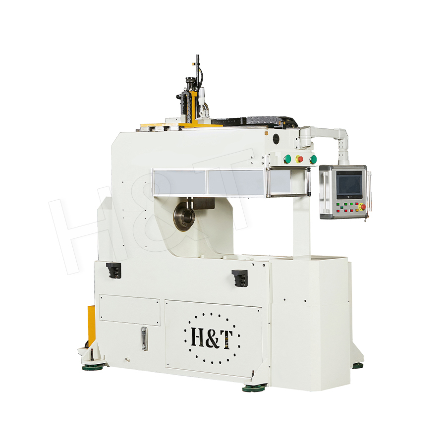
No. 196, Lifa Avenue, Haian City, Nantong, Jiangsu Province, China
News Category
Product Category
What is a Spiral Coil Bending?
Spiral coil bending is a specialized metal-forming process that shapes tubing — typically copper or steel — into continuous helical or multi-turn coil structures using guide rollers, adjusting rollers, and precision control systems. The result is a compact, high-surface-area coil (commonly called a spiral tube or coil tube) used as the core heat exchange element in HVAC systems, industrial heat exchangers, fan coil units, and more. The process is executed by dedicated spiral coil bending machines that can control pitch, outer diameter, bending angle, and coil length in a single continuous operation.
Unlike simple tube bending, spiral coil bending demands precise multi-axis coordination. A tube that is bent incorrectly — with wall thinning, ovality, or irregular pitch — will underperform thermally or fail under pressure cycling. That is why understanding the fundamentals of this process is essential for engineers specifying heat exchanger components and procurement managers sourcing coil-bending equipment.
Content
- 1 How Spiral Coil Bending Works: The Core Mechanism
- 2 Primary Applications of Spiral Coil Bending
- 3 Key Performance Parameters: A Comparison
- 4 Materials Processed in Spiral Coil Bending
- 5 Types of Spiral Coil Bending Machines
- 6 Quality Control in Spiral Coil Bending
- 7 Spiral Coil Bending vs. Other Tube Forming Processes
- 8 Design Considerations When Specifying a Spiral Coil
- 9 Industry Standards and Codes Relevant to Spiral Coil Bending
- 10 Gipfel: Custom Spiral Coil Bending Solutions for Global Markets
- 11 Frequently Asked Questions About Spiral Coil Bending
How Spiral Coil Bending Works: The Core Mechanism
A spiral coil bending machine feeds straight tubing through a series of forming stations. Each station plays a specific role:
- Feed rollers — drive the tube forward at a controlled speed.
- Guide rollers — constrain the tube and define the bending plane.
- Bending rollers — apply radial force to create the desired coil diameter.
- Pitch adjustment mechanism — incrementally shifts the tube axially to produce the helical spacing (pitch) between turns.
Modern CNC-controlled spiral coil bending machines can store multiple coil programs and switch between them automatically. Key parameters set during programming include:
- Coil outer diameter (OD) — typically ranges from 50 mm to over 600 mm depending on application.
- Pitch — the axial distance between adjacent turns; affects flow velocity and pressure drop on the shell side.
- Number of turns — determines total tube length and therefore total heat exchange area.
- Tube OD and wall thickness — copper tube from 6 mm to 32 mm OD is common; steel tube up to 50 mm OD is processed on heavier machines.
The bending radius ratio (BRR = coil radius / tube OD) is a critical quality indicator. A BRR below 3 risks excessive wall thinning on the outer arc and wrinkling on the inner arc. Most heat exchanger specifications call for a BRR of 4 or higher to maintain structural integrity under repeated thermal cycling.
Primary Applications of Spiral Coil Bending
1. Heat Exchanger Manufacturing
The dominant application of spiral coil bending is the production of helical coil heat exchangers. Compared to straight-tube shell-and-tube designs, a spiral coil offers 30–50% more heat transfer area per unit of shell volume due to the secondary flow (Dean vortex) effect generated by the curvature. This vortex continuously disrupts the boundary layer, increasing the heat transfer coefficient without increasing tube length or pump energy.
Common heat exchanger types that rely on spiral coil bending include:
- Air-to-water heat exchangers — used in HVAC air handling units (AHUs) and rooftop equipment.
- Steam-to-water heat exchangers — common in district heating substations where steam condenses on the shell side and heats domestic hot water in the coil.
- Immersion coil heaters — submerged in tanks containing process fluids, solvents, or water for indirect heating.
- Waste heat recovery coils — installed in flue gas ducts or exhaust streams to recover thermal energy that would otherwise be lost.
- Refrigeration evaporator and condenser coils — bent to fit the geometry of refrigeration cabinets, cold rooms, and chillers.

2. Fan Coil Units in Central Air Conditioning
A fan coil unit (FCU) is one of the most widespread HVAC terminal devices. It consists of a small centrifugal or axial fan and a heat exchange coil through which chilled water (for cooling) or hot water (for heating) circulates. The spiral or serpentine coil — produced by coil bending — is the thermal heart of the FCU.
In a typical commercial building FCU:
- Chilled water enters the coil at approximately 7°C and leaves at around 12°C.
- Room air passes over the coil surface, losing heat and moisture to the cold water stream.
- The coil's finned copper tube construction — where the copper tube is first spiral-bent, then fin-stacked — allows a 3-row or 4-row coil to deliver cooling capacities from 0.5 kW to over 10 kW in a compact cassette form.
3. Industrial Pipeline Layout and Instrumentation
In process plants, power stations, and shipbuilding yards, piping systems include instrument tubing, sensing lines, hydraulic tubes, and small-bore process lines that must navigate around structural members and equipment. Spiral coil bending machines allow fabricators to produce expansion loops, sensing coils (pigtails), and pre-formed instrumentation assemblies in a single automated pass — eliminating multiple fittings and reducing the risk of leak points.
For example, a sensing coil (also called a pigtail siphon) made from 12 mm OD stainless steel tube is spiral-bent to approximately 50 mm coil diameter and installed upstream of a pressure transmitter to protect it from high-temperature steam. This is a direct product of spiral coil bending.
4. Solar Thermal and Geothermal Energy Systems
In solar thermal collectors, copper spiral coils are embedded in or bonded to absorber plates to carry the heat transfer fluid. In geothermal ground source heat pump systems, spiral coil bending machines produce compact horizontal "slinky" coils that are laid in shallow trenches, achieving up to 3× the heat exchange area of straight pipe per linear meter of trench — a significant land-area saving.
Key Performance Parameters: A Comparison
The table below compares straight-tube and spiral coil configurations for the same shell-side duty, illustrating why spiral coil bending is often the preferred choice in compact heat exchanger design.
| Parameter | Straight Tube Design | Spiral Coil Design |
|---|---|---|
| Heat Transfer Area (same shell volume) | Baseline (1×) | 1.3× – 1.5× |
| Overall Heat Transfer Coefficient (U) | Baseline | +20–40% higher due to Dean vortex |
| Footprint / Shell Length | Longer shell required | Compact; shorter shell |
| Number of Fittings / Joints | Many tube sheets, fittings | Fewer joints; lower leak risk |
| Thermal Expansion Accommodation | Requires expansion joints | Self-compensating via coil flexibility |
| Cleaning / Maintenance | Easy mechanical cleaning | Chemical cleaning preferred |
| Fabrication Complexity | Moderate | Requires spiral coil bending machine |
Materials Processed in Spiral Coil Bending
The choice of tube material strongly influences both the bending process parameters and the final coil's service life. The most commonly processed materials are:
- Copper (C11000, C12200) — the most common material for HVAC and refrigeration coils. Its high thermal conductivity (385–400 W/m·K), excellent formability, and corrosion resistance make it ideal. Copper tube can be bent to BRR values as low as 3 without wrinkling when properly annealed.
- Carbon steel — used in industrial heat exchangers, boilers, and pressure vessel coils. Wall thinning control is more critical than with copper; minimum BRR is typically 5–6 for seamless carbon steel tube.
- Stainless steel (304, 316L) — selected for corrosive fluid duties, food and beverage, and pharmaceutical applications. Work-hardening during bending requires higher bending forces and careful springback compensation.
- Aluminum — used in lightweight heat exchangers for automotive and HVAC applications. Aluminum's low density and moderate conductivity (160–205 W/m·K) make it suitable for air-cooled coils.
- Titanium — for seawater and aggressive chemical environments. Titanium's strength-to-weight ratio is exceptional, but its springback requires sophisticated CNC compensation algorithms in the bending machine controller.
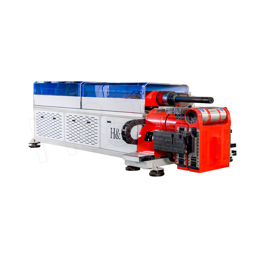
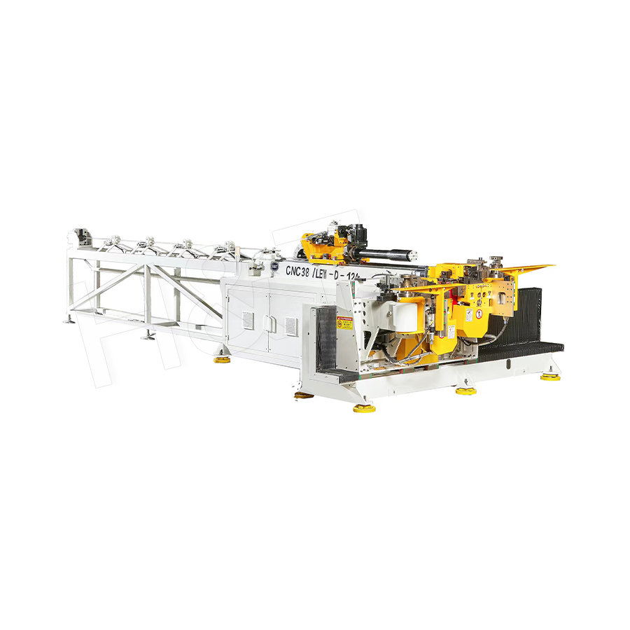
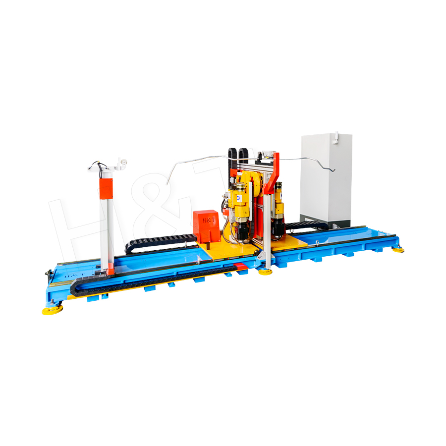
Types of Spiral Coil Bending Machines
The market offers several machine configurations, each suited to a different production context:
Manual and Semi-Automatic Coil Benders
Suited to small workshops and prototype fabrication. The operator adjusts roller positions manually and monitors pitch by sight. Output quality depends heavily on operator skill; batch consistency can vary by ±2–3 mm in coil diameter across a production run. Suitable for simple copper coils in small HVAC repair shops.
CNC Spiral Coil Bending Machines
The standard for modern production. CNC machines store dozens of coil programs and execute them with repeatability of ±0.1 mm on coil diameter and ±0.5 mm on pitch. Servo-driven feed and bending axes allow rapid changeover — typically under 15 minutes for a different coil specification. These machines are standard in factories producing fan coil units, heat exchangers, and refrigeration evaporators at volumes above a few hundred units per month.
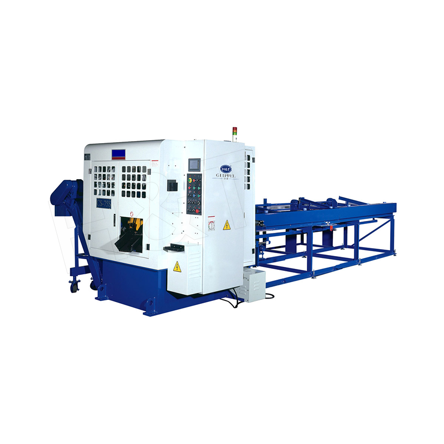
Multi-Head and Combined Processing Lines
High-throughput applications pair spiral coil bending with inline operations: tube straightening, cutting to length, end-forming (flaring, beading, swaging), and automatic stacking. A fully integrated line can produce a finished, inspected coil every 30–90 seconds, enabling lights-out manufacturing for high-volume HVAC component suppliers.
Heavy-Duty Industrial Coil Benders
Designed for thick-wall steel or stainless steel tube used in pressure vessels, boiler headers, and chemical plant coils. These machines feature rigid frames, high-torque hydraulic drives, and induction heating systems that pre-heat the tube locally to reduce bending stress and minimize wall thinning on tube ODs up to 100 mm or more.
Quality Control in Spiral Coil Bending
A properly bent spiral coil must meet both dimensional and metallurgical standards. The following quality checks are standard in professional coil bending operations:
- Coil OD and ID measurement — verified with a calibrated go/no-go gauge or digital calipers at first-off and periodically during the run. Tolerance is typically ±1% of nominal OD for heat exchanger coils.
- Pitch uniformity — measured across all turns; a variation greater than ±1 mm can cause uneven flow distribution on the shell side and hot spots.
- Ovality check — the cross-section of the tube at the bend should not deviate from round by more than 8% (per ASME B31.1 for power piping). Excessive ovality increases pressure drop and may cause fatigue cracking.
- Wall thickness measurement — ultrasonic thickness gauging at the outer arc of the first, middle, and last turns to verify that wall thinning does not exceed the design allowance (typically 12.5% for pressure vessels per ASME).
- Hydrostatic or pneumatic pressure test — completed coils are pressurized to 1.5× design pressure and held for a defined duration to confirm leak tightness before dispatch.
- Visual and dye-penetrant inspection — for stainless and titanium coils, surface cracks introduced by work-hardening are checked with liquid penetrant testing (PT).
Spiral Coil Bending vs. Other Tube Forming Processes
It is helpful to distinguish spiral coil bending from related processes to select the correct equipment and technique:
| Process | Output Geometry | Typical Application | Key Limitation |
|---|---|---|---|
| Spiral coil bending | Multi-turn helix / annular coil | Heat exchangers, FCUs, expansion loops | BRR limitation; requires mandrel for thin wall |
| Single-plane CNC tube bending | 2D multi-bend profiles | Automotive brake lines, furniture frames | Cannot produce continuous helix |
| 3D CNC tube bending | Complex 3D routed tubes | Aerospace, motorsport exhaust | Slow; high cost per bend |
| Roll bending (ring rolling) | Single large-radius arc or ring | Pipe arch bending, structural rings | Cannot produce multi-turn helix or pitch |
| Hydroforming | Complex hollow sections | Automotive structural parts | Not suited to continuous coil production |
Design Considerations When Specifying a Spiral Coil
Engineers and procurement teams specifying spiral coils for heat exchanger or HVAC applications should address the following parameters early in the design process:
- Thermal duty (kW) and LMTD — determine the required heat transfer area and therefore the number of turns and coil diameter.
- Operating pressure and temperature — dictate tube material, wall thickness, and whether the coil must comply with ASME, EN 13480, or another pressure code.
- Fluid compatibility — refrigerants, brines, and aggressive chemicals may require stainless steel or titanium rather than copper.
- Allowable pressure drop — a tighter coil (smaller pitch) increases shell-side velocity and pressure drop; the pitch must be balanced against pumping energy cost.
- Physical envelope — the coil OD and length must fit within the shell or duct available; spiral coil bending allows custom coil geometries to match non-standard vessel dimensions.
- Connection type — coil ends may require flared fittings, brazed couplings, threaded connections, or flanged headers, which the coil bending supplier should form as part of the same manufacturing sequence.
Industry Standards and Codes Relevant to Spiral Coil Bending
Spiral coils used in pressure-bearing equipment must comply with applicable codes. The most frequently referenced standards include:
- ASME BPVC Section VIII Div. 1 — governs unfired pressure vessel design; includes rules on maximum allowable wall thinning in bends (12.5% of nominal wall).
- ASME B31.1 / B31.3 — power piping and process piping codes; specify bend quality acceptance criteria for ovality and wall thinning.
- EN 13480 — European standard for metallic industrial piping; includes equivalent bend quality requirements.
- ASTM B280 / EN 12735 — copper tube specifications for air conditioning and refrigeration, defining dimensional tolerances that affect coil bending setup.
- ISO 9001 — quality management system requirements that reputable coil bending machine manufacturers and coil fabricators hold as a baseline certification.
Gipfel: Custom Spiral Coil Bending Solutions for Global Markets
Selecting the right spiral coil bending machine — or the right OEM coil bending partner — is as important as understanding the process itself. Gipfel is a high-tech enterprise that specializes in tube processing equipment and automation solutions, integrating R&D, manufacturing, sales, and service under one roof.
Operating an advanced production facility supported by a multimedia demonstration center, Gipfel is equipped with large-scale CNC machining centers, gantry machining centers, and high-precision testing equipment — infrastructure that directly ensures the dimensional stability and mechanical accuracy of every spiral coil bending machine produced.
As a dedicated Custom Spiral Coil Bending Supplier and OEM/ODM Spiral Coil Bending Company, Gipfel upholds the principle that "quality is the foundation of a company, and innovation is the source of its growth." This philosophy is realized through:
- Strict process control — every machine undergoes full-parameter calibration and run-off testing before shipment.
- Continuous technological innovation — Gipfel's R&D team develops advanced CNC control algorithms that address springback compensation, multi-material flexibility, and integration with automated production lines.
- Customized and intelligent solutions — OEM and ODM customers receive machines engineered to their specific tube diameter range, coil geometry requirements, and production throughput targets.
- Global competitiveness — Gipfel's solutions help customers in HVAC manufacturing, heat exchanger production, and industrial piping fabrication maintain a technology and cost advantage in demanding international markets.
Whether you are sourcing a standalone CNC spiral coil bending machine, a fully integrated tube processing line, or a turnkey OEM coil supply arrangement, Gipfel provides the engineering expertise, manufacturing capability, and after-sales service infrastructure to support your project from concept through commissioning.
Frequently Asked Questions About Spiral Coil Bending
What tube diameter range can spiral coil bending machines handle?
Most general-purpose CNC spiral coil bending machines process copper or steel tube from 6 mm OD to 50 mm OD. Heavy-duty models extend this range to 100 mm OD or more for industrial pressure vessel coils. Custom machines can be built for micro-tube coils below 4 mm OD used in medical devices and laboratory heat exchangers.
Is a mandrel required for spiral coil bending?
For thin-walled tubes (wall thickness less than approximately 5% of tube OD), an internal mandrel or plug is recommended to prevent the tube from collapsing inward during bending. Most HVAC copper tube (wall 0.5–1.0 mm, OD 9.52–19.05 mm) is bent without a mandrel by maintaining a BRR above 4. Thicker-wall industrial tubes generally do not require mandrels.
How is pitch consistency maintained in high-speed production?
On CNC machines, the pitch axis is driven by a servo motor synchronized with the feed axis via closed-loop control. Encoder feedback from both axes is compared in real time, and the controller makes micro-corrections at a rate of hundreds of times per second. This approach maintains pitch uniformity to ±0.3 mm even at production speeds of 8–15 m/min.
What is the difference between a coil bending machine and a fin and tube assembly line?
A spiral coil bending machine forms the bare tube into a helix. A fin-and-tube assembly line is a downstream process where aluminum or copper fins are stacked over straight or hairpin tubes, then mechanically expanded. These are complementary but distinct processes. Spiral coils in immersion heaters and shell-and-coil heat exchangers are typically used without fins; fan coil and air handler coils use fins but are usually serpentine, not spiral.
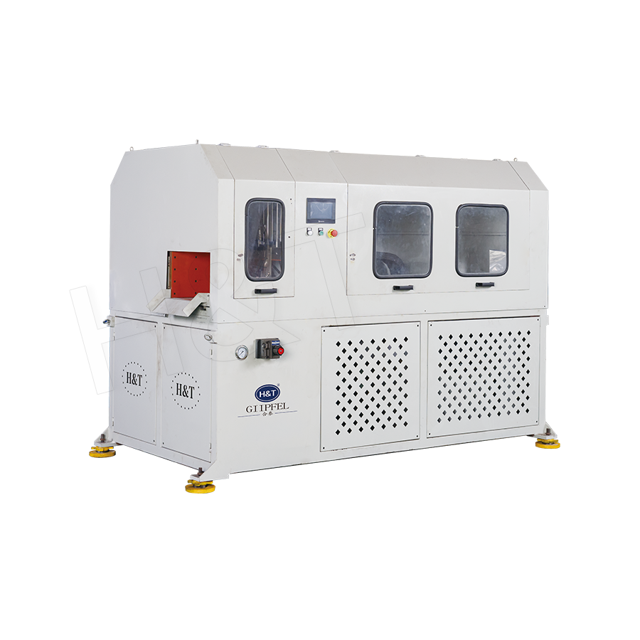
Featured Products
A Complete Range of Tube Processing Solutions
Precision Tube Bending
 Ready To Customise
Your Bent Tube Products?

Your Bent Tube Products?
Proprietary software, smart control systems, and 50+ patents ensure more efficient and intelligent production at every step.
Copyright © 2025 by Gipfel Precision Machinery Co.,Ltd All Rights Reserved. Precision Tube Machinery Manufacturer | Pipe Forming, Cutting, End Forming Solutions
